Hardware Reference
In-Depth Information
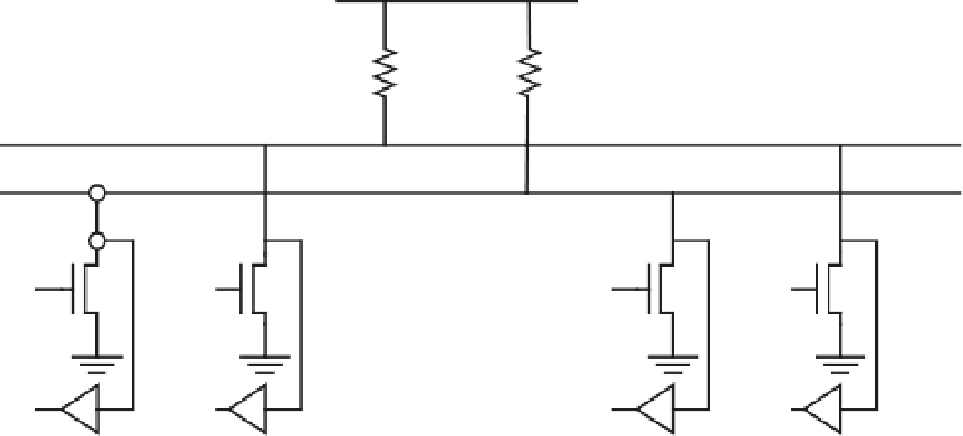
+V
DD
R
P
R
P
SDA line
SCL line
CLK1
OUT
CLK2
OUT
Data1
OUT
Data2
OUT
CLK1
IN
CLK2
IN
Data1
IN
Data2
IN
Device 1
Device 2
Figure 11.1
■
Connecting standard- and fast-mode devices to the I
2
C bus
An I
2
C data transfer consists of the following fundamental signal components:
•
Start (
S
)
•
Stop (
P
)
•
Repeated start (
R
)
•
Data
•
Acknowledge (
A
)
S
TART
(S) C
ONDITION
A start condition indicates that a device would like to transfer data on the I
2
C bus. As
shown in Figure 11.2, a start condition is represented by the SDA line going low when the
clock (SCL) signal is high. The start condition will initialize the I
2
C bus. The timing details for
the start condition will be taken care of by the microcontroller that implements the I
2
C bus.
Whenever a data transfer using the I
2
C bus is to be initiated, the designer must tell the micro-
controller that a start condition is wanted.
SDA
SCL
Figure 11.2
■
I
2
C start condition


Search WWH ::

Custom Search