Hardware Reference
In-Depth Information
HCS12
MAX6952
MAX6952
DOUT
DIN
DOUT
DIN
MOSI0
OSC
OSC
C
SET
C
SET
SCK0
CLK
CLK
I
SET
I
SET
PM5
CS
CS
R
SET
R
SET
MISO0
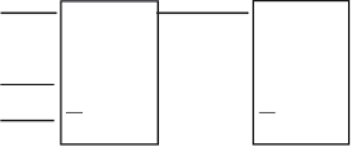
Figure 10.30
■
HCS12 driving two MAX6952s
Solution:
The SPI0 module should be configured with the following features:
•
12-MHz baud rate
•
Master mode with interrupts disabled
•
Shift data on the rising edge with clock idle low
•
Shift data out most significant bit first
•
Disable mode fault
•
Stop SPI0 on wait mode
Two MAX6952 chips should be configured as follows:
Intensity10 register
We set the intensity of both MAX6952s to maximum by sending out the following value:
0x01, 0xFF, 0x01, 0xFF
Sixteen bits need to be written to each MAX6952, of which the upper 8 bits are the address to
select the Intensity10 register.
Intensity32 register
Set the second and third displays to maximum intensity by sending the same data as to
Intensity10:
0x02, 0xFF, 0x02, 0xFF
Scan-limit register
Confi gure the MAX6952 to drive four monocolor displays by writing the following value to the
MAX6952:
0x03, 0x01, 0x03, 0x01
; drive four displays
Configuration register
Confi gure this register to
•
Select P1 blink phase
•
Not to clear digit data on both plane P0 and P1


Search WWH ::

Custom Search