Hardware Reference
In-Depth Information
Master mode
MSTR = 1
Slave mode
MSTR = 0
When SPE = 1
Serial Out
MOSI
Serial In
MOSI
Normal
mode
SPC0 = 0
SPI
SPI
Serial In
MISO
Serial Out
MISO
SWOM enables open-drain output
SWOM enables open-drain output
Serial Out
Serial In
MOMI
Bidirectional
mode
SPC0 = 1
SPI
SPI
BIDIROE
BIDIROE
Serial In
Serial Out
SISO
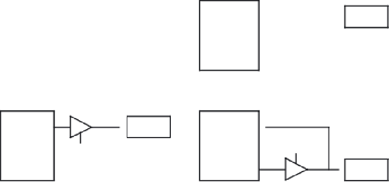
Figure 10.7
■
Normal mode and bidirectional mode
In the special case where the MODFEN bit is cleared, the SS
x
pin is a general-purpose I/O
pin for the SPI system configured in master mode. In this special case, the mode fault func-
tion is prohibited and the MODF flag remains cleared. In case the SPI system is configured as a
slave, the SS
x
pin is a dedicated input pin. Mode fault error does not occur in slave mode.
When a mode fault error occurs, the MSTR bit in the SPI
x
CR1 is cleared, the MODF bit in
the SPI
x
SR register is set, and the output enable for the SCK
x
, MISO
x
, and MOSI
x
pins are de-
asserted. If the mode fault error occurs in the bidirectional mode for an SPI system configured in
master mode, output enable of the MOMI pin is cleared if it was set but SISO is not affected. No
mode fault error occurs in the bidirectional mode for the SPI system configured in slave mode.
The HCS12 has two low-power modes and the SPI module behaves differently in these two
modes.
SPI
IN
W
AIT
M
ODE
SPI operation in wait mode depends on the state of the SPISWAI bit in the SPI
x
CR2
register.
•
If the SPISWAI bit is cleared, the SPI operates normally when the CPU is in wait
mode.
•
If the SPISWAI bit is set, the SPI clock generation ceases and the SPI module
enters a power conservation state when the CPU is in the wait mode. If the SPI is
configured as a master, any transmission and reception in progress stops at wait
mode entry. The transmission and reception resumes when the SPI exits wait mode.


Search WWH ::

Custom Search