Hardware Reference
In-Depth Information
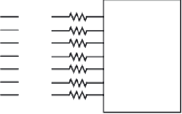
HCS12
470
Ω
each
a
a
b
c
d
e
f
g
common cathode
PB6
PB5
PB4
PB3
PB2
PB1
PB0
f
b
g
e
c
d
Figure 4.17
■
Driving a single seven-segment display
Decimal
Digit
Segments
Corresponding Hex Number
a b c d e f g
Figure 4.17 Circuit
Dragon12 Demo Board
0
1 1 1 1 1 1 0
$7E
$3F
1
0 1 1 0 0 0 0
$30
$06
2
1 1 0 1 1 0 1
$6D
$5B
3
1 1 1 1 0 0 1
$79
$4F
4
0 1 1 0 0 1 1
$33
$66
5
1 0 1 1 0 1 1
$5B
$6D
6
1 0 1 1 1 1 1
$5F
$7D
7
1 1 1 0 0 0 0
$70
$07
8
1 1 1 1 1 1 1
$7F
$7F
9
1 1 1 1 0 1 1
$7B
$6F
Table 4.7
■
Decimal to seven-segment decoder
The circuit in Figure 4.18 can display up to six digits by utilizing the time-multiplexing
technique, in which each seven-segment display is lighted in turn briefly and then turned off.
When one display is lighted, all other displays are turned off. Within one second, each seven-
segment display is lighted and then turned off many times. Because of the
persistence of vision
,
all six displays will appear to be lighted simultaneously.
Example 4.13
▼
Write an instruction sequence to display 7 on the seven-segment display #5 in Figure 4.18.
Solution:
To display 7 on display #5, we need to
•
Output the hex value $07 to Port B
•
Set the PP5 pin to low
•
Set pins PP4 through PP0 to high


Search WWH ::

Custom Search