Graphics Programs Reference
In-Depth Information
V
T
2ψ
2
--------------
log
(
1
⁄
P
fa
)
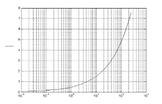
Figure 2.3. Normalized detection threshold versus probability of false alarm.
T
fa
=
t
int
⁄
P
fa
(2.20)
where represents the radar integration time, or the average time that the
output of the envelope detector will pass the threshold voltage. Since the radar
operating bandwidth
t
int
B
is the inverse of
t
int
, then by substituting Eq. (2.19)
into Eq. (2.20) we can write
T
fa
as
V
2
2ψ
2
1
---
T
fa
=
exp
---------
(2.21)
Minimizing means increasing the threshold value, and as a result the radar
maximum detection range is decreased. Therefore, the choice of an acceptable
value for
T
fa
T
fa
becomes a compromise depending on the radar mode of opera-
tion.
Fehlner
1
defines the false alarm number as
ln
P
fa
()
ln
()
-------------
n
fa
=
--------------------------
≈
(2.22)
ln
(
1
P
fa
)
1. Fehlner, L. F.,
MarcumÓs and SwerlingÓs Data on Target Detection by a Pulsed
Radar
, Johns Hopkins University, Applied Physics Lab. Rpt. # TG451, July 2, 1962,
and Rpt. # TG451A, September 1964.


Search WWH ::

Custom Search