Graphics Programs Reference
In-Depth Information
40
35
30
25
20
15
10
5
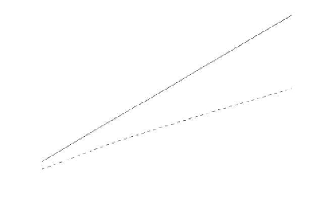
Coherent integration
Non-coherent integration
0
-5
10
0
10
1
10
2
10
3
10
4
Number of integrated pulses
Figure 1.22. SNR improvement when integration is utilized.
1.8.1. Transmit and Receive Losses
Transmit and receive losses occur between the radar transmitter and antenna
input port, and between the antenna output port and the receiver front end,
respectively. Such losses are often called plumbing losses. Typically, plumbing
losses are on the order of 1 to 2 dB.
1.8.2. Antenna Pattern Loss and Scan Loss
So far, when we used the radar equation we assumed maximum antenna
gain. This is true only if the target is located along the antennaÓs boresight axis.
However, as the radar scans across a target the antenna gain in the direction of
the target is less than maximum, as defined by the antennaÓs radiation pattern.
The loss in SNR due to not having maximum antenna gain on the target at all
times is called the antenna pattern (shape) loss. Once an antenna has been
selected for a given radar, the amount of antenna pattern loss can be mathemat-
ically computed.
For example, consider a antenna radiation pattern as shown in
Fig.
1.23.
It follows that the average antenna gain over an angular region of
sin
x
⁄
x
±
θ 2
⁄
about the boresight axis is
----
2
θ
2
π
r
λ
------
G
av
≈
1
(1.88)
36


Search WWH ::

Custom Search