Graphics Programs Reference
In-Depth Information
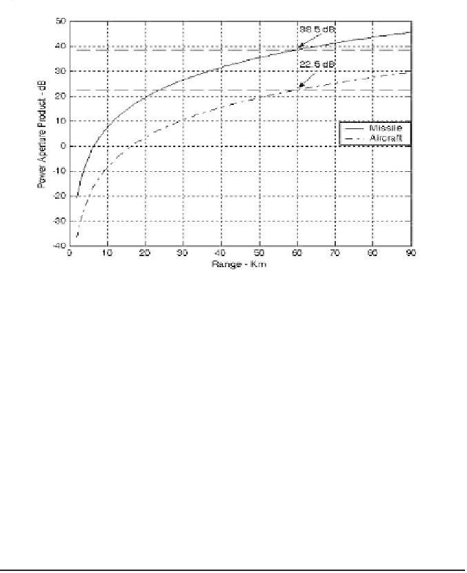
Figure 1.17. Power aperture product versus detection range for
radar in mini design case study 1.1.
Use as the radar operating frequency. Then by using
we calculate using Eq. (1.40) . Now one must deter-
mine the antenna azimuth beamwidth. Recall that the antenna gain is also
related to the antenna 3-dB beamwidth by the relation
f
0
=
2.0
GHz
1.75
m
2
A
e
=
G
=
29.9
dB
26000
θ
e
θ
a
G
=
---------------
(1.78)
where are the antenna 3-dB azimuth and elevation beamwidths,
respectively. Assume a fan beam with
(
θ
a
,
θ
e
)
θ
e
=
Θ
E
=
15°
. It follows that
26000
θ
e
G
26000
θ
a
=
---------------
=
----------------------------
=
2 . 6 6 °
⇒
θ
a
=
46.43
mrad
(1.79)
10
×
977.38
1.7. Pulse Integration
When a target is located within the radar beam during a single scan it may
reflect several pulses. By adding the returns from all pulses returned by a given
target during a single scan, the radar sensitivity (SNR) can be increased. The
number of returned pulses depends on the antenna scan rate and the radar PRF.
More precisely, the number of pulses returned from a given target is given by
θ
a
T
sc
f
r
2π
n
P
=
-----------------
(1.80)
Search WWH ::

Custom Search