Graphics Programs Reference
In-Depth Information
Once the required SNR is computed, Eq. (1.57) can then be used to find the
most suitable pulse (or waveform) that achieves the required SNR (or equiva-
lently the required ). Often, it may be the case that none of the available
radar waveforms may be able to guarantee the minimum required SNR for a
particular RCS value at a particular detection range. In this case, the radar has
to wait until the target is close enough in range to establish detection, otherwise
pulse integration (coherent or non-coherent) can be used. Alternatively, cumu-
lative probability of detection can be used. All these issues will be addressed in
Chapter 2.
P
D
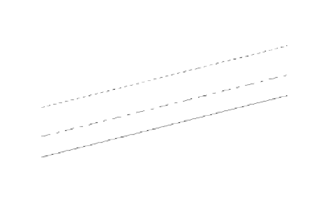
10
3
R = 75 Km
R = 100 Km
R = 150 Km
10
2
10
1
0
10
10
-1
5
10
15
20
Minimum required SNR - dB
Figure 1.13. Pulsewidth versus required SNR for three different detection
range values.
1.5.1. Radar Reference Range
Many radar design issues can be derived or computed based on the radar ref-
erence range which is often provided by the radar end user. It simply
describes that range at which a certain SNR value, referred to as , has to
be achieved using a specific reference pulsewidth for a pre-determined
target cross section, . Radar reference range calculations assume that the
target is on the line defined by the maximum antenna gain within a beam
(broad side to the antenna). This is often referred to as the radar line of sight, as
illustrated in
Fig. 1.14.
R
ref
SNR
ref
τ
ref
σ
ref
The radar equation at the reference range is


Search WWH ::

Custom Search