Graphics Programs Reference
In-Depth Information
Rectangular Grid with Circular Boundary Arrays
The far field electric field associated with this configuration can be easily
obtained from that corresponding to a rectangular grid. In order to accomplish
this task follow these steps: First, select the desired maximum number of ele-
ments along the diameter of the circle and denote it by
N
d
. Also select the
associated element spacings
d
x
,
d
y
. Define a rectangular array of size
N
d
×
N
d
. Draw a circle centered at
(
xy
,
)
=
(
00
,
)
with radius
r
d
where
N
d
2
1
r
d
=
--------------- ∆
x
+
(8.68)
and . Finally, modify the weighting function across the rectangular
array by multiplying it with the two-dimensional sequence
∆
xd
x
≤
⁄
4
amn
(
,
)
, where
1
,
if dis to
(
m n
,
)
th element
<
r
d
amn
(
,
)
=
(8.69)
0
;
elsewhere
where distance,
, is measured from the center of the circle. This is illus-
dis
trated in Fig. 8.36.
amn
(
,
)
=
1
dis
>
r
d
amn
(
,
)
=
0
dis
<
r
d
amn
(
,
)
=
1
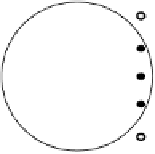
Figure 8.36. Elements with solid dots have
; other elements
amn
(
,
)
=
0
have
.
Hexagonal Grid Arrays
The analysis provided in this section is limited to hexagonal arrays with cir-
cular boundaries. The horizontal element spacing is denoted as
d
x
and the ver-
tical element spacing is
3
2
d
y
=
-------
d
x
(8.70)


Search WWH ::

Custom Search