Graphics Programs Reference
In-Depth Information
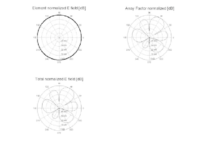
Figure 8.33. Element, array factor, and total pattern for the circular array
defined in the table on bottom of page 346.
Concentric Grid Circular Arrays
The geometry of interest is shown in
Fig. 8.19d
and
Fig. 8.34.
In this case,
elements are distributed equally on the outer circle whose radius is ,
while other elements are linearly distributed on the inner circle whose
radius is . The element located on the center of both circles is used as the
phase reference. In this configuration, there are
N
2
a
2
N
1
a
1
N
1
++
N
2
1
total elements in
the array.
The array pattern is derived in two steps. First, the array pattern correspond-
ing to the linearly distributed concentric circular arrays with and ele-
ments and the center element are computed separately. Second, the overall
array pattern corresponding to the two concentric arrays and the center element
are added. The element pattern of the identical antenna elements are consid-
ered in the first step. Thus, the total pattern becomes,
N
1
N
2
E
θφ
(
,
)
=
E
0
θφ
(
,
)
+
E
1
θφ
a
1
(
,
;
)
+
E
2
θφ
a
2
(
,
;
)
(8.67)
Fig. 8.35
shows a 3-D plot for concentric circular array in the
θφ
,
space for
the following parameters:
Search WWH ::

Custom Search