Graphics Programs Reference
In-Depth Information
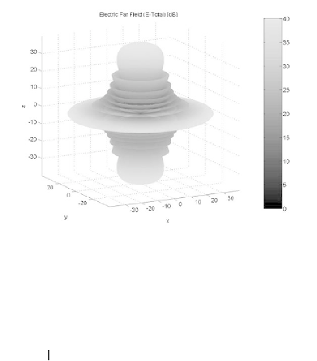
Figure 8.5d. Three-dimensional plot for the radiation pattern in Fig. 8.5a.
Solving for
ψ
yields
λ
m
d
-------
ψ
m
=
asin
±
;
m
=
012…
,,,
(8.38)
where the subscript is used as a maxima indicator. The first maximum
occurs at , and is denoted as the main beam (lobe). Other maxima
occurring at are called grating lobes. Grating lobes are undesirable and
must be suppressed. The grating lobes occur at non-real angles when the abso-
lute value of the arc-sine argument in Eq. (8.38) is greater than unity; it follows
that . Under this condition, the main lobe is assumed to be at
(broadside array). Alternatively, when electronic beam steering is considered,
the grating lobes occur at
m
ψ
0
=
m
0
≥
1
d
<
λ
ψ
=
0
λ
n
d
------
sin
ψ
sin
ψ
0
=
±
;
n
=
12…
,,
(8.39)
Thus, in order to prevent the grating lobes from occurring between
±
90°
, the
element spacing should be
d
<
λ 2
⁄
.
The radiation pattern attains secondary maxima (sidelobes) when the numer-
ator of Eq. (8.35) is maximum, or equivalently


Search WWH ::

Custom Search