Graphics Programs Reference
In-Depth Information
2
1
N
2
sin
(
(
Nkd
sin
ψ
)
⁄
2
)
)
2
G
(
sin
ψ
)
=
E
n
(
sin
ψ
=
------
-----------------------------------------------
(8.35)
sin
(
(
kd
sin
ψ
)
⁄
2
)
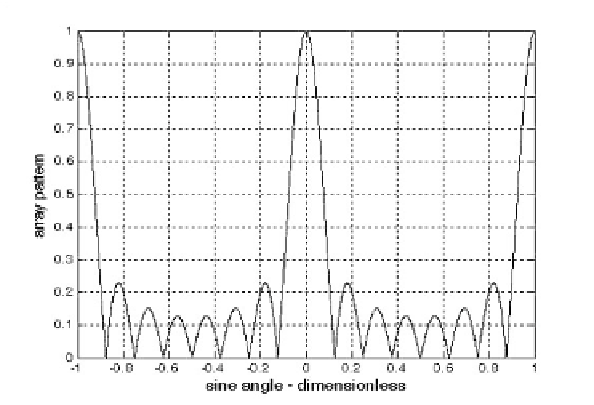
Fig. 8.5
shows a plot of Eq. (8.35) versus for . The radiation
pattern has cylindrical symmetry about its axis , and is
independent of the azimuth angle. Thus, it is completely determined by its val-
ues within the interval . This plot can be reproduced using MAT-
LAB program
Ðfig8_5.mÑ
given in Listing 8.1 in Section 8.8.
sin
θ
N
=
8
G
(
sin
ψ
)
(
sin
ψ
=
0
)
(
0 ψπ
<<
)
The main beam of an array can be steered electronically by varying the
phase of the current applied to each array element. Steering the main beam into
the direction-sine is accomplished by making the phase difference
between any two adjacent elements equal to
sin
ψ
0
kd
sin
ψ
0
. In this case, the normal-
ized radiation pattern can be written as
sin
[
(
Nkd
⁄
2
)
(
sin
ψ
sin
ψ
0
)
]
2
1
N
2
------
------------------------------------------------------------------------
G
(
sin
ψ
)
=
(8.36)
sin
[
(
kd
⁄
2
) ψ
(
sin
sin
ψ
0
)
]
If then the main beam is perpendicular to the array axis, and the array
is said to be a broadside array. Alternatively, the array is called an endfire array
when the main beam points along the array axis.
ψ
0
=
0
The radiation pattern maxima are computed using LÓHopitalÓs rule when
both the denominator and numerator of Eq. (8.35) are zeros. More precisely,
kd
sin
2
ψ
------------------
=
±
m
π
;
m
=
012…
,,,
(8.37)
N
=
8
d
=
λ
Figure 8.5a. Normalized radiation pattern for a linear array;
;
.


Search WWH ::

Custom Search