Graphics Programs Reference
In-Depth Information
)
2
P
c
2πσ
2
(
ωω
0
-----------------
S
c
()
=
exp
-----------------------
(7.2)
2σ
2
σ
2
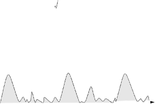
where is the total clutter power; and were defined earlier. Fig. 7.1
shows a typical PSD sketch of radar returns when both target and clutter are
present. Note that the clutter power is concentrated around DC and integer
multiples of the PRF.
P
c
ω
0
spectrum
clutter returns
target
return
n
ois
e
l
evel
f
r
f
r
frequency
f
=
0
Figure 7.1. Typical radar return PSD when clutter and target are present
.
7.2. Moving Target Indicator (MTI)
The clutter spectrum is normally concentrated around DC ( ) and mul-
tiple integers of the radar PRF , as illustrated in
Fig. 7.2a.
In CW radars, clut-
ter is avoided or suppressed by ignoring the receiver output around DC, since
most of the clutter power is concentrated about the zero frequency band.
Pulsed radar systems may utilize special filters that can distinguish between
slowly moving or stationary targets and fast moving ones. This class of filter is
known as the Moving Target Indicator (MTI). In simple words, the purpose of
an MTI filter is to suppress target-like returns produced by clutter, and allow
returns from moving targets to pass through with little or no degradation. In
order to effectively suppress clutter returns, an MTI filter needs to have a deep
stop-band at DC and at integer multiples of the PRF.
Fig. 7.2b
shows a typical
sketch of an MTI filter response, while
Fig. 7.2c
shows its output when the
PSD shown in Fig. 7.2a is the input.
f
=
0
f
r
MTI filters can be implemented using delay line cancelers. As we will show
later in this chapter, the frequency response of this class of MTI filter is peri-
odic, with nulls at integer multiples of the PRF. Thus, targets with Doppler fre-


Search WWH ::

Custom Search