Graphics Programs Reference
In-Depth Information
Stepped Frequency Waveforms
163
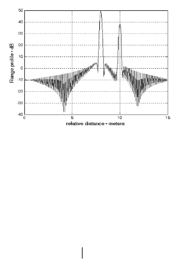
Figure 3.14. Synthetic range profile for three scatterers. The first and third
scatterers appear in the same FFT bin.
The additional phase term present in Eq. (3.74) distorts the synthesized range
profile. In order to illustrate this distortion, consider the SFW described in the
previous section, and assume the three scatterers of the first case. Also, assume
that .
Fig. 3.15
shows the synthesized range profile for this case.
Comparisons of
Figs. 3.11
and 3.15 clearly show the distortion effects caused
by the uncompensated target velocity.
Figure 3.16
is similar to Fig. 3.15 except
in this case, . Note in either case, the targets have moved from
their expected positions (to the left or right) by
v
=
100
ms
⁄
v
=
100
ms
⁄
(1.28
Disp
=
2
×
nv
×
⁄
PRF
m).
This distortion can be eliminated by multiplying the complex received data
at each pulse by the phase term
τ
1
2
2
c
2
c
------
iT
Φ
=
exp
2π
f
i
++
-----
-------
(3.75)
and are, respectively, estimates of the target velocity and range. This pro-
cess of modifying the phase of the quadrature components is often referred to
as Ðphase rotation.Ñ In practice, when good estimates of and are not avail-
able, then the effects of target velocity are reduced by using frequency hopping
between the consecutive pulses within the SFW. In this case, the frequency of
each individual pulse is chosen according to a predetermined code. Waveforms
of this type are often called Frequency Coded Waveforms (FCW). Costas
waveforms or signals are a good example of this type of waveform.
ô
ô
ô
ô


Search WWH ::

Custom Search