Environmental Engineering Reference
In-Depth Information
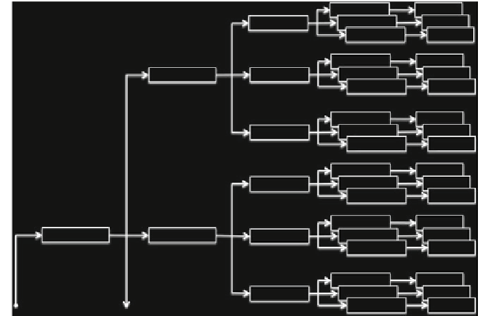
Fig. 5.3
Second-level structure for multi-model forecast system. Each hydrodynamic model drives
multiple oil spill models with different IC and different oil spill model parameters, providing
multiple forecasts that can be used for probability map visualizations. This figure is expanded detail
of highlighted portion of Fig.
5.2
Hydrodynamic models present a greater challenge, but can be implemented using
separate logical processors of a single workstation for separate models (where
N
hydro
is small) or with multiple networked workstations (where
N
hydro
is large). The num-
ber of hydrodynamic models can be reduced if the uncertainty contributions in the
wave model and hydrodynamic model parameters can be minimized; indeed, if these
can be neglected the only uncertainty driving hydrodynamics will be wind forecast,
so that
N
hydro
=
=
1, and the number of hydrodynamic models is simply
N
wind
and the total number of oil spill models is
N
wind
N
IC
N
oil
. A key point is that
multiple hydrodynamic models are only needed after a spill has occurred; that is only
a single hydrodynamic model is necessary to minimize
initial condition uncertainty
of spin-up (Sect.
5.4
). Thus, if new forecast data is available every 3h and a 72h
forecast is desired, computational power must be continuously available to run a
single hydrodynamic simulation at least 24
N
wave
faster than real time. Additional com-
putational resources are only needed when a spill occurs and the full multi-model
forecast system is invoked.
The proposed operational forecast system described above is effectively
static
;
that is, it provides the data for a single animation of a probability field for an oil spill
location based on data available at the initiation of the modelling. However, during
an emergency there will be new COS data and updated wind forecasts available
×


Search WWH ::

Custom Search