Graphics Reference
In-Depth Information
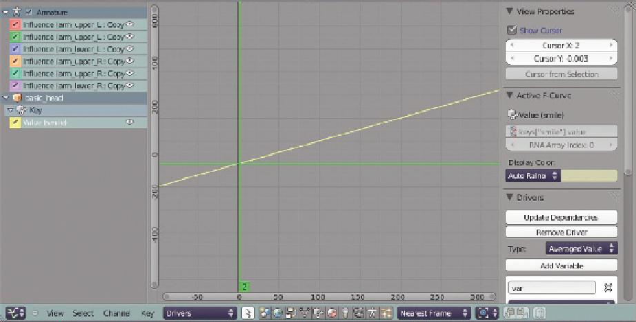
Figure 10.5
The Graph Editor, for setting a shape key driver.
object (use the Object properties panel), and name it appropriately (“smile control”). Select the head, RMB
on the Value slider of the shape you're working with, and choose
Add Driver
. Here's where things
deviate a bit from the previous instructions. We will be adding the control property to the armature object,
even though the shape we're driving is on the head mesh.
Figure 10.5
shows the Graph Editor set to
display Drivers. Note that it shows not only the mesh smile one we just created, but the other ones we
attached to the armature during rigging too. The Mouse Cursor button immediately to the right of the
Drivers/F-curve selector on the header toggles this behavior. When enabled, the Graph Editor only displays
curves for the selected object. Otherwise, it shows everything as in the figure.
Making sure that the smile value driver channel is selected in the Graph Editor, show the N-key properties
panel and click
Add Variable
in the
Drivers
section. Set
Type
to
Averaged Value
. Set the
Value
object below to your armature by clicking the field beside it and using the Object browser. If you remem-
ber from Chapter 8, the last step is to copy the data path of the custom property and paste it into the
Path
field. To do this, you first need to select the armature object in the 3D view. With the armature
object selected, its Custom Properties are displayed once again, and you can RMB on the smile property
and copy its data path. Then, you reselect the mesh, make sure that the smile value driver is selected, and
paste the data path into the Variable section.
That might seem like a long way to go just to control one Value slider (the shape key smile value) with
another (the custom property smile slider). You are not wrong. However, the first advantage is that when
you add custom properties and drivers for each shape key, you get access to all of them in one convenient
Search WWH ::

Custom Search