Graphics Reference
In-Depth Information
simulation that needs an underlying structure in order to deform, there is no need for that body. The
clothes themselves become the body.
Some people will spend days or even weeks trying to model the perfect head or human figure, but spend
only the barest amount of time on clothing that character. This is obviously a mistake (and yet it happens),
as for the most part, the clothes are what will be seen. Carefully constructed and animated clothes
imply
the correct body structure underneath—they make its existence assumed and believable even though there
is nothing there. Fortunately, the structure of clothing is simpler than heads and hands.
In real life clothing is made by starting with flat pieces of fabric that are cut apart in patterns, then fastened
together (usually stitched) so that they drape properly on the body. The great news for 3D artists is that
this means you don't have to worry about funky loop structures. Fabric is basically a grid, and this lets
you work with fairly uniform grid-type primitives when making clothing. For our character, let's construct
a simple long-sleeved shirt with a v-neck and collar.
Shirt
Observation
Depending on your skill level with artistic observation, you may or may not be able to sit down
and draw a collared Oxford shirt without using a reference. If you find that you can't, it's almost
certain that although you “know” what one looks like, you've never really observed one in enough
detail to reproduce it. Search for some reference images (or pull one from a closet in your home)
and take a look. A standard Oxford is made from seven different sections, pieced together. While
you don't need to replicate this method of manufacture, a subdivided cylinder with appropriate
extrusions and cutouts will suffice. A careful observation will go a long way to informing your
result in 3D.
To begin the shirt add a tube
(Shift-A), and in the Tweak
panel uncheck
Cap Ends
.
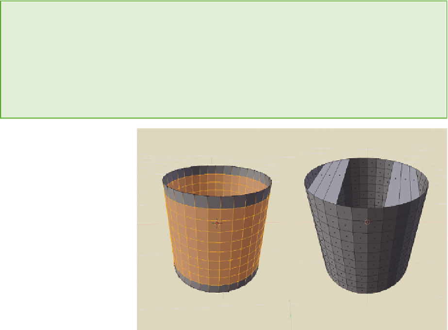
Use the Loop Cut tool (Ctrl-
R, mouse wheel) to add
something like nine cuts
around the circumference of
the tube. This will make a
nice, even grid structure,
shown in
Figure 6.19
. Also
highlighted in the figure are
several sets of vertices along
the top edge of the tube. By
selecting these vertices in sets
of four—two from the front
and two from the back—and
Figure 6.19
A tube is added, and several edges along the top are joined to create faces.
Search WWH ::

Custom Search