Graphics Reference
In-Depth Information
Divide your main modeling area into
two distinct windows by dragging from
either of the action zones as you learned
to do in Chapter 2. Set one to front view
(
Numpad-1
) and one to side view
(
Numpad-3
). Hover the mouse over
one of them and press the
N
key to bring
up the view options. Scrolling down to
the bottom of the panel, you will find a
section called
Background Image
,
which is shown in
Figure 6.3
. Enable the
panel by checking the box next to the
label, then LMB click the
Add Image
button. Expand the controls by clicking
the triangle to the left of the Not Set
notifier. LMB click the
Image Open
button and browse to your front view
reference in the file browser. After select-
ing an image, you will see it in the 3D
view. Use the
Scale
and
Offset
controls
to interactively adjust the image so that
it lines up closely with the model of the
head.
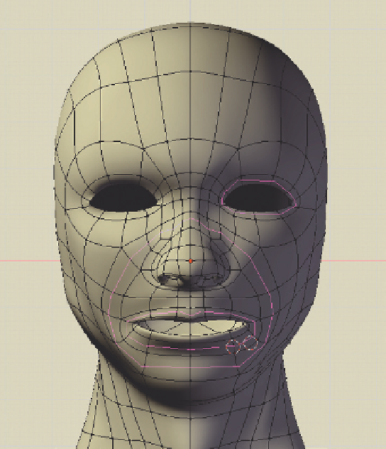
Figure 6.2
The base head model, with crucial loops highlighted.
Use the
N
key again to hide the View/
Properties panel. Repeat the process in
the other 3D view, this time choosing your other sketch
or reference image. The goal is to have two 3D views, one
for adjusting from the front, and one for adjusting from the
side.
Now, it is a matter of using the modeling tools to make
the rough structure of the base head fit the contours of the
reference pictures.
The best way to proceed is to begin in the front view.
Switch to Edit mode (
Tab
key) and show wireframes (
Z
key, as opposed to solid view). Use the
O
key to enable
Proportional Edit Falloff
(PEF). With those things in
order, select the outer vertices and try to make the front
view contour match the one in your reference. You'll
notice as you work on the base head that it is in fact a
Figure 6.3
The Background Image controls.

Search WWH ::

Custom Search