Agriculture Reference
In-Depth Information
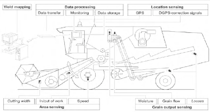
Fig. 12.1
Subsystems for site-specifi c yield recording in a combine harvester
Filtering, analyzing and mapping of the geo-referenced yield data is normally
realized on the offi ce computer with specifi c software.
For the fi rst time Bae et al. (
1989
) automatically recorded grain yields and the
position of the combine harvester in a fi eld using a yield measurement system and a
radio beacon positioning system.
A comprehensive overview on systems for yield sensing of combinable crops,
forage crops and root crops was presented by Demmel in Schmidhalter et al. (
2005
).
12.3
Yield Measurement for Combinable Crops
For yield detection within combine harvesters, several grain output sensors have been
developed, evaluated and introduced into practical use. They work on the continuous
fl ow principle and are installed in the upper part or in the head of the clean grain
elevator (Auernhammer et al.
1993
). The measuring systems on the market are
either based on the volume fl ow principle or on the mass fl ow principle (Fig.
12.2
).
With the
volume fl ow measurement principle
, the mass of the grain output is
obtained by converting volume fl ow via specifi c gravity or specifi c density into
mass fl ow. The volume is recorded by determining the grain pile volume on the
elevator paddles.
The fi rst continuously working yield measurement system on the market, which
is not in production any more, used a paddle/bucket wheel with a magnetic clutch
that was fed from a widened elevator head serving as a hopper (Claydon Yield-O-
Meter, Fig.
12.2
, system 1). As soon as enough grain was in the hopper, the paddle
wheel started turning and conveyed the material into the grain auger. The frequency
of the buckets was detected and provided the volume fl ow. This was converted into