Agriculture Reference
In-Depth Information
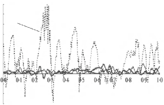
plow + pto driven harrow 12 mm MWD
plow + drawn tines 15 mm MWD
plow only 95 mm MWD
plow
+ pto driven harrow
+600
plow only
plow + drawn tines
+400
+200
0
time in s
-200
0.2
0.6
1.0
1.4
distance in m
Fig. 7.8
Signals on the sensing tine for three different tilths of a clay soil (From Bogrekci and
Godwin
2007b
, supplemented and altered).
MWD
mean mass diameter of soil clods
In principle, soil clod sensing is
impact sensing
. Almost every clod in a seedbed
is a unique case in terms of size, mass and shape. Therefore, the impacts delivered
by the clods on the recording tine must vary constantly. The sensitivity of the
sensing instruments including the cultivator tine must allow for indicating this.
An investigation of several spring tine types in this respect showed that the tine type
as shown in Fig.
7.7
gave the best results.
An important factor of cultivator tines is the
rake angle
, which is the angle
between the tine part operating in the soil and the undisturbed soil surface, seen
perpendicular to the direction of travel. The lower the rake angle is, the smaller the
soil resistance is in most cases. However, the larger the rake angle is, the more the soil
is broken up. This is, because with a larger rake angle it is more diffi cult for the
clods to pass the tine, hence the soil resistance as well as the break-up are higher.
The tine in Fig.
7.7
left has a rake angle of approximately 90°, which is a com-
mon angle in implements for secondary cultivation. Bogrekci and Godwin (
2007b
)
have shown that using a 90° rake angle enables the soil break-up to be distinguished
more effectively than when using smaller angles. This as well probably is due to the
fact, that the clods cannot go around the tine as easy as with smaller angles, and this
improves their recording.
In Fig.
7.8
, the forces recorded by the sensing tine are shown for a soil, which
was either only ploughed or secondary cultivated as well. The secondary cultivation
was either by a drawn tined harrow or by a harrow that was operated via the power-
take-off (pto). All curves show a
high resolution
on a time basis. They hold for a
travel speed of 5 km/h. Since the duration is 1 s, the length of travel represented by
the abscissa in Fig.
7.8
is about 1.4 m. Within this distance, all curves of the three