Environmental Engineering Reference
In-Depth Information
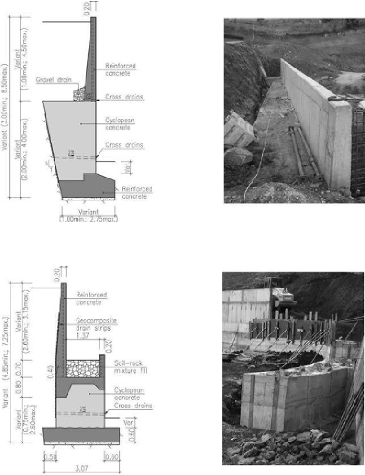
Figure 6.
Retaining structure with semi-gravity section.
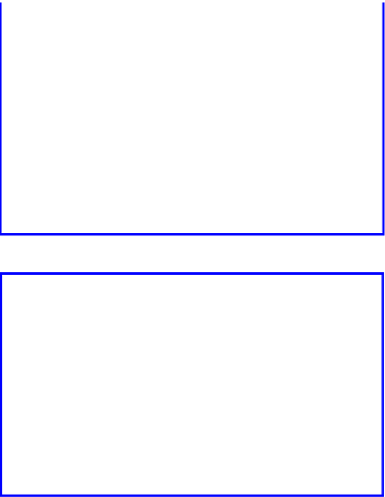
Figure 7.
Retaining structure in U-shape.
This activity revealed itself very effective, allow-
ing to proceed, in due time, to several design retain-
ing structures' adaptation, taking advantage of the
real geological and geotechnical conditions, that in
some areas, revealed to be more favorable than the
ones assumed during the design phase. on the other
hand, it allowed to effectively solve some problems
raised during the execution phase resulting from the
local geological conditions.
concerning to the importance of the techni-
cal assistance, in addition to other optimizations
made, it could be stand out the reduction of the
concrete volume in some walls, through the reduc-
tion of their foundations width and the cutback
on the soil nails quantity for the excavation slopes.
This step was adopted based on the soil nails pull-
out tests' results, defined under the final design
scope, and visual inspection of the slopes to
consolidate.
several pull-out tests were executed evenly on
the resort different blocks' areas, to measure the
pulling-out force by length unit, fundamental
parameter when designing soil nails (Freitas
et al.
,
2006). in most oh these tests was concluded that
the pulling-out force by length unit was superior
than the one considered in the design, information
that allowed to adjust some slopes' soil nails meshes
to 1,75V:1,5h and 2V:1,5h. This optimization,