Environmental Engineering Reference
In-Depth Information
element. nevertheless, to improve its behaviour
with regard to possible tractions or fissures which
could arise, a reinforced grating was included with
three levels of bars measuring 25 mm in diameter.
a fundamental aspect analysed in this artifi-
cial stratum is its weight since it is located over
an area which is particularly sensitive to possi-
ble overloads. With the objective of not applying
overloads any greater than those which already
existed, it was recommended to use concrete made
of light aggregate which enables achieving very
low densities and concrete with resistance of up
to 25 MPa.
it was required that the stratum be constructed
in one go to avoid any type of discontinuities which
is why it was intended for the three levels of rein-
forcing to be positioned in one go.
as a precautionary measure the area located
within the cave under the vertical of the improved
stratum had to be dismantled while work was being
performed on the surface and while waiting for the
concrete to achieve its resistance over 28 days.
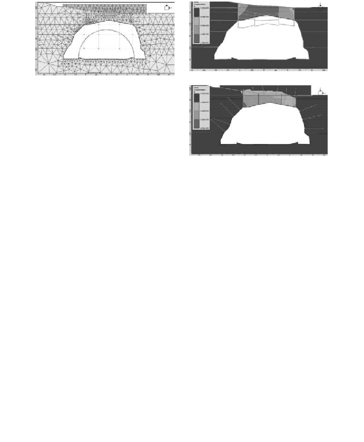
likewise, to make a more simplified analysis of
the effect of this stratum, two finite element mod-
els were made which included joining elements to
reproduce the generation of one joint throughout
the rock solid mass.
in the first calculation model the formation of
the auditorium up to its present condition is repro-
duced in successive phases. in the final phase of
the calculation a long-term hypothetical situation
is simulated in which the resistant and deforma-
tional characteristics of the vertical joints are
reduced until achieving the instability of the calcu-
lation model. The second model is exactly the same
as the first. The only difference is that in the last
phase the improved concrete stratum is added and
the bolts to verify that this reinforcement manages
to stabilise the arch of the auditorium.
be clearly seen in blocks which can be seen to have
become detached from the solid mass. nevertheless,
those which show signs of unfavourable fractures
and which have welding in their planes on the sur-
face or not must also be considered as sensitive.
5.2.1
Solutions type 2-A: Micro-seaming
of blocks
For the largest blocks of approximately 1 cubic
meter a weight was estimated of approximately
40 kn. They had to be considered as entirely sup-
ported by the treatment to be used given that ini-
tially the behaviour and orientation of the fracture
planes is uncertain, especially at depth with there
could even be the possibility of gaps appearing
(bubbles).
The treatment of these blocks was carried out
partially with the injection treatment discussed in
the previous solutions. This treatment, however,
is complemented by using the micro-seaming of
blocks and also by using fiberglass rods injected
suing epoxy resins.
For diameters which are commercially available,
the working load of the rods was calculated by using
a safety coefficient of 1.6 (maximum value which is
usually applied to conventional anchoring).
With the range of loads considered, the treat-
ment was planned with a diameter of 8 mm, with
the objective of making the hole as small as possi-
ble (approx. 2 mm in addition to the rod diameter).
in the case of the largest blocks it would therefore
be necessary to use two or three rods positioned in
such a way as to take full advantage of the capac-
ity of the rod (i.e. as parallel as possible to the
5.2
Isolated solutions: Solutions type 2
These are solutions which aim to secure blocks
from 10 centimeters up to 1 m
3
which could become
detached from the rock solid mass being in a strict
equilibrium situation. This strict equilibrium can