Environmental Engineering Reference
In-Depth Information
signals along the discontinuities or vacuols. com-
pact breccias occurred generally from moderately
to very weathered, with moderate to close fractures.
Disaggregated breccias occur from completely to
highly weathered, with very close fractures. Tuffs
are less representative and occur from moderately
to highly weathered. sometimes the compact and
disaggregated breccias and the tuffs present signifi-
cant thickness.
5
cRoss-secTions
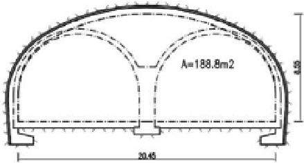
Figure 11.
Wide cross-sections of tunnels.
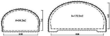
The cross-sections of the current tunnels have a
minimum effective width between walls of 9,0 m
for unidirectional tunnels (highway) and 9,6 m for
bidirectional tunnels (expressways), with two lanes
of 3,5 m each and variable heights, depending on
the super elevation of the cross-section but with a
minimum gabarit of 5 m.
The contour is formed by a semicircular arch
roof vertically prolonged by the walls (horse-shoe
two old tunnels of the highway near Funchal (João
Gomes and Jardim Botânico tunnels) the cross-
section was formed by an horizontally elongated
and inferiorly truncated ellipsis roof. More recently
in a few tunnels it has been adopted a curved sec-
tion (Pontinha tunnel).
adopted in tunnels with three lanes and effective
width of 12 m (Pestana Júnior tunnel) and four
lanes and effective width of 18.5 m (santa cruz
West and east tunnels).
Frequently it is necessary to include near the
portals deceleration and acceleration lanes, which
leads to wide cross-sections with three lanes in
João abel de Freitas tunnel and four lanes in
ening of this tunnel was necessary for reasons of
execution of new roads on two phases near the
Faial connection.
6
PRiMaRY anD seconDaRY lininG
in general, based on lythological, structural and
mechanical characteristics of the formations and of
the corresponding longitudinal and cross-sectional
geotechnical profiles, a geotechnical zoning on the
rock mass is performed in the design stages which
comprise three or four classes, being the behaviour of
the material increasingly worse, corresponding to a
good, medium, poor or very poor behaviour. For this
geotechnical zoning a geomechanical classification is
prepared, mainly based on Bieniawski (1989) and
aFTes (2003), in which the quality of the roof, side
walls and invert is predicted. This allows a classifica-
tion of each zone in one of the five possible classes,
to which is associated a certain rock mass quality.
This zoning cannot be considered accurate, due
to significant lateral variation of the type and char-
acteristics of the volcanic formations, along the
tunnel length and the cross-section. The classifica-
tion of a unique section could have variations, from
good to very poor, whether we consider the roof, the
walls or the invert. nevertheless, it permits to estab-
lish at the design stage, with sufficient accuracy, the
application zones for each type of support.
For the construction stage the sequential exca-
vation Method has been used. in this method,
commonly known by naTM, the definition of the
type and the way of application of primary lining
is a function of the knowledge of the rock mass
behaviour from the observation and experience
gained during execution. in the support's design it
is considered that it is flexible enough to tolerate
the possible deformations of the rock mass with-
out absorbing great efforts.
The shotcrete has become the most recommend-
able support system by its initial high resistance, its
easy and immediate application, its inter-action with
the rock, establishing a sealing surface, and the pos-
sibility of being placed with a variable and reduced
Figure 9.
current cross-sections of tunnels.
Figure 10.
special cross-sections of tunnels.