Environmental Engineering Reference
In-Depth Information
water ph values (5,5 to 6,5), according to water
physicochemical analysis. The pumping station
final lining comprises reinforced concrete walls
(e = 0,50 m), topped by a semi-circular vault
(e = 0,50 m) with an inner section of 5,50 m radius.
The total height is about 26 m, having a strut in the
middle, materialized by the ground floor slab.
2.5
Instrumentation and observation
considering the specific aspects of the project,
the geotechnical and geological conditions of the
site, and the spatial configuration of the cavern, an
instrumentation plan was defined in order to allow:
i) evaluation of safety during construction works;
ii) comparison between the design assumptions
and the observed behaviour; iii) extrapolation of
the behaviour from the early stages of excavation
to the later ones, in order to modify and adapt, if
necessary, the construction methodology and the
structural solutions according to the observed dis-
placements of the rock mass.
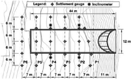
in order to achieve this purpose, six instrumen-
tation profiles were defined, with a distance of
7 m between them, which allowed measuring the
following quantities: i) superficial settlements—24
settlement gauges; ii) sub-surface vertical move-
ments—six extensometer rods with two reading
points each; iii) lateral movements—four inclinom-
eters; iv) and convergences—through the use of
several survey points. The location of these instru-
ments is shown in Figures 8 and 9.
Figure 8.
Plan of monitoring profiles.
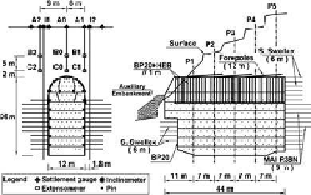
Figure 9. Geometry and instrumentation profiles: a)
cross section; b) longitudinal profile.
3
PRoJecT chaRacTeRisTics
oF WaTeR sToRaGe anD aUXiliaRY
TUnnels
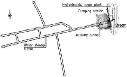
Water storage tunnel has 1250 m length, and a
transversal section of 7 m × 5 m, in order to store
40,000 m
3
of water. The longitudinal inclination is
0,01%.
The tunnel alignment was defined during the
execution phase, searching the formations with
the best geological and geotechnical characteristics
in terms of stability and water-tightness, reducing
also the associated costs; therefore several branches
were executed, easing the vehicles circulation inside
and allowing the creation of several work fronts
The auxiliary tunnel function is to give access
to the water storage tunnel and to the pumping
station, in order to execute maintenance and
inspection works, being also used as an access dur-
ing the construction phase. This tunnel has 73 m
long and a cross-section of 5,5 m × 5,5 m, being
horizontal in the initial 10 m, having then a 13,5%
inclination up to the water storage tunnel.
Figure 10.
Water storage tunnel alignment.
The primary support was defined in the entire
perimeter, working also as a final lining—in Table 2
the adopted solutions are defined, presenting in
Figure 11 the ZG2 geotechnical zone correspond-
ing sections. concerning the execution phasing,
the ZG1 zone was excavated in full face (in the
areas with worst characteristics advances were
made from 10 to 10 m in the higher half-section),
while in the ZG2 and ZG3 zones the excavation
was executed first in the higher half-section and
only afterwards in the lower half-section—in these