Environmental Engineering Reference
In-Depth Information
red-coloured and about 1 m of residual soil has
formed at the top of a thick phonolitic pyroclastic
unit. The soil horizon is overlaid by a thick lava
flow. sample Rs3 is a red soil that was taken from
the top of the Tigaiga massif at a site called
'Mirador de sergio' The Rs3 unit exposes several
fault planes that dip eastwards and black slicken-
sides are clearly visible. The emplacement of both
pyroclastic units predates the large orotava land-
slide, dated at ∼0.56 Ma BP.
The results of the basic testing of the residual
soils have already been published: hürlimann et al.
(2001) analyse the weathered ignimbrite while del
Potro and hürlimann (2009) present the study of
the hydrothermally altered summit soils. here we
present a summary and compare both soils as well
as the results of further, more complex geotechnical
tests.
3.2
Results
3.2.1
General characterization
General soil properties are summarised in Table 1.
X-ray difractograms of the fine fraction of the
tested samples show the presence of secondary clay
mineralisation in the residual soils (see
Table 1
). soil
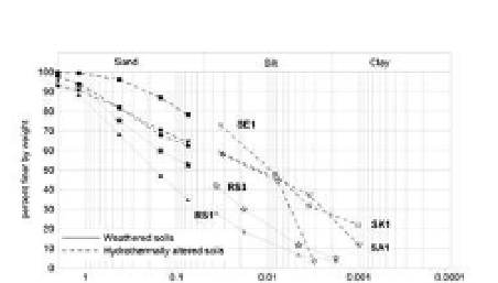
particle distributions in Figure 2 show a significant
clay fraction only for hydrothermally altered soils.
Plasticity values are given in Table 1. Finally, the
soil was classified according to the Unified soil
classification system, Uscs: residual soils from
the weather ignimbrites are medium plasticity
sands (sP) and soils from hydrothermal alteration
are medium plasticity silts (Mh).
3
GeoTechnical chaRacTeRisaTion
3.1
Methodology
To fully characterise the properties of the resid-
ual soils collected we have performed a series
of
geochemical
and
geotechnical
tests
and
measurements.
X-ray refraction (XRD) was performed on all
samples to characterise the main mineral assem-
blages present in each case. Furthermore, a sample
of unaltered phonolite was also analysed to pro-
vide a baseline measurement. Grain size distribu-
tions and plasticity tests were also performed for
all soil samples, as was a general soil characteri-
sation. consolidation tests were performed on two
different settings. Weathered soil Rs1 was tested in
an oedometer with normal loads of up to 1600 kPa.
consolidation of the hydrothermally altered soils
(sa1, se1 and sk1) was tested during the load-
ing of the sample probes prior to direct shear tests.
in this way only the initial load is carried out on
an undisturbed sample, and further tests are on
sheared samples. all soil units except Rs3 were
tested in strain-controlled, consolidated, drained,
direct shear and ring shear tests. For both tests
normal loads were in the range 50-600 kPa, and
strain rates were: ∼0.005 and ∼0.089 mm/min for
the direct shear and ring shear tests respectively.
Weathered unit Rs1 was further tested in a high-
normal load shear box where normal loads ranged
5.2-15.59 MPa.
in addition to the tests described above, Rs1
was also tested in triaxial conditions. Two dif-
ferent apparatus were used. a standard GDs
stress-path system including a Bishop-Wesley
hydraulic cell for pressures up to 1.7 MPa, and
an in-house built larger apparatus for pressures
up to 5 MPa. Two different tests have been car-
ried out: consolidated-undrained tests (hereafter
cU-tests) and consolidated-drained tests (here-
after cD-tests). The former provides undrained
shear strength of the soil alongside the increase
in pore water pressure in the probe. The latter
provide drained shear strength as well as volu-
metric strain behaviour.
3.2.2
Consolidation analysis
The analysis of the consolidation curves obtained
from the oedometer tests on sample Rs1 has given
Table 1. General properties, plastici and main composition
from XRD of the soil samples collected, respectively.
natural
density
[g/cm3]
Dry
density
[%]
Void
ratio
[-]
liquid
limit
[%]
Plasticity
index
[%]
XRD main
component*
soil
sa
1.69
0.99
1.78
64.37
28.03
al-ka
se
1.56
1.23
1.22
al-ka
sk
1.56
0.91
1.97x 71.75
30.57
Felds-ka
Rs1 1.53
1.24
1.40
n/a
n/a
Felds-ha
* al: alunite, ka: kaolinite; Felds: feldspars;
ha: halloysite.
Figure 2.
soil particle distribution of the soils from
Tenerife.