Environmental Engineering Reference
In-Depth Information
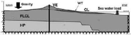
The bi-dimensional finite difference modelling
(FDM) was performed by Flac 5.0 code (itasca),
the finite element (FeM) by siGMa/W code
(Geoslope international), along the WnW-ese
section, crossing the volcano summit and the Valle
del Bove depression, with a horizontal extent of
61 km and to the depth of 10 km (
Fig. 1
).
1) volcanic edifice (Ve), 2) subetnean clays (cl),
3) apennine-Maghrebian flysh (Flcl), 4) hyb-
lean plateau (hP), 5) intrusive complex (Dc). The
boundary conditions were imposed by fixing x- and
y-velocities equal to zero respectively at the base
and side boundaries of the model. sea water load
was taken into account, and the hydrogeological
conditions assumed considering first a dry model
and then with Flcl and hP completely saturated
ing has an average resolution of 100 m, and it is
adjusted to fit the topography and the main units.
a first phase of analysis consisted in the initiali-
zation of the stress field in elastic conditions under
the effect of gravity alone.
Then, a second phase consisted in an elastic-
plastic equilibrium under the effect of gravity. in
this phase the lithotechnical units were assigned
a Mohr-coulomb constitutive law and the asso-
ciated strength and deformability properties in
selected value ranges. hoek-Brown properties were
order to evaluate the effect of the main assump-
tions concerning: i) topographic complexity;
ii) geometry and asymmetry of the model; iii)
role of the distance of boundary condition from
the area of interest; iv) geometry of the contact
between hP and Flcl (
Fig. 5
); v) rheology and
constitutive laws attributed to the lithotechnical
3.1
FDM
3.1.1
Conceptual model and sensitivity analysis
The conceptual model was first simplified and
progressively implemented to analyse the effect
of topography, geometry and rheological behav-
iour of the structural units. Five main geologi-
cal and lithotechnical units were considered:
Figure 4. Geological-technical conceptual model. The
vertical black line indicates the location of the inter-
face for the application of magma pressures. at the
sides, boundary conditions (fixed x- or y-velocities) are
imposed. The white dots indicate the average depth at
which equivalent Mohr-coulomb parameters are calcu-
lated as a function of the confining stress.
Table 1. Material properties assigned in the analyses. if multiple values are indicated, sensitivity analyses were
performed.
lithotechnical units
Ve
Fl/Flcl
cl
hP
elastic rock mass properties
Dry unit weight, γ(kn/m
3
)
2500
2600
2300
2700
elastic modulus, e (GPa)
4; 25
6.6; 16
1.9; 10
25
0.3
0.28
0.28
0.28
Poisson ratio, υ
Mohr-coulomb properties calculated at the specified minimum confining stress σ
3
σ
3
(MPa)
17
22
5
-
cohesion, c (MPa)
3.55
5; 2.9; 1;
1
-
Friction angle, φ°
33
29; 30
29
-
Tensile strength, σ
t
(MPa)
0.035
0.036
0.126
-
0
0
0
-
Dilation angle, δ°
hoek-Brown rock mass properties
Ucs* (MPa)
65
100
50
-
s coefficient
0.0013
0.0067
0.0016
-
mb parameter
2.346
2.0046
0.6300
-
a coefficient
0.511
0.5040
0.5099
-
Disturbance factor D
0
0
0
-
* Uniaxial compressive strength.