Environmental Engineering Reference
In-Depth Information
S
j
S
C
,d
a)
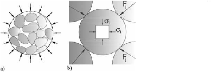
b)
Figure 3. layout of the forces on a contact (a); stress
in the contact.
Figure 2. isotropic compression test. (a) Reticular
structure. (b) Detail of particle with the contact forces.
if
λ
and
µ
are average coefficients, then:
where
σ
i
is an average isotropic stress to which the
intact rock is subjected as the result of an effect of
the exterior isotropic pressure,
p
.
Both works have to be equal,
T
i
=
T
e
, so:
σ
i
∆
V
i
=
p
∆
V
then:
λP
=
Q
µDP
=
M
where
Q
and
P
are the transverse and normal force
respectively and
M
is the average flexural moment
in the contact.
in the contact between particles there is an aver-
age stress,
σ
c
, defined by:
∆
∆
V
V
σ
i
=
p
i
admitting that ∆
V
i
/
V
i
= ∆
V/V
(volumetric defor-
mation of the intact rock equals the total), gives:
P
S
S
SN
p
n
=
p
wn
(2)
σ
c
==
1
−
(
−
)
c
c
R
R
p
V
V
1
σ
i
==
−
p
1
n
i
R
The average isotropic stress,
σ
i
, to which the
intact rock particles were submitted are transferred
through forces
F
j
which operate on the contacts
between the other particles connected to them
mal force,
P
j
, a tangential force,
Q
j
, and a flexural
coefficients
λ
and
µ
are defined as:
NS
S
c
w
=
Maximum
and
minimum
normal
stresses
(
σ
M
and
σ
m
, respectively) are:
P
S
µ
D
d
=
D
d
Q
j
=
λ
j
P
j
M
j
=
µ
j
DP
j
where D is the size of the particle.
P is displaced a distance µD from the centre of
the contact.
if n is the coordination number (number of
contacts of the particle), then:
(3)
σ
=
1
+
σ µ
1
+
M
c
c
P
S
µ
D
d
=
D
d
(4)
σ
=
1
−
σ µ
1
−
m
c
c
where
d
= diameter of the contact.
The maximum shear in the contact is:
=
3
2
NP
=
Sσ
i
where P is the average value of the normal compo-
nents of the contact forces. Then:
(5)
τ
λσ
M
c
according to equations (2), (3) (4) and (5):
D
d
p
wn
S
N
S
N
p
n
(1)
σ
=+
1
µ
P
=
σ
=
M
i
(
−
)
1
−
R
R