Biomedical Engineering Reference
In-Depth Information
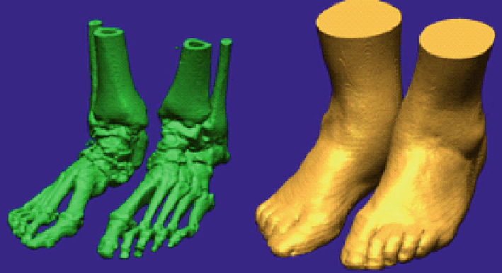
Bone structure and soft tissues from CT by Mimics
®
Fig. 9
for obese individual
to a CAD software, like Solidworks
®
,CATIA
®
or Rapidform
®
, being afterwards
edited and improved, resulting in a solid part for each 3D object. Since foot bone
structure is complex, being difficult for the software to generate surfaces along all
the structure, it is necessary to divide anatomically the bone structure into five
pieces: tibia and fibula; calcaneous and talus; cuboid, cuneiforms and navicular;
metatarsals and phalanges, separately. A solid part for all these individual objects is
generated (Fig.
10
). Finally, by combining them, results in a unified bone structure,
which was assembled together with the soft tissue and a rigid support under the foot
whose purpose was to simulate the ground (Fig.
11
).
3.3
Numerical Simulation: Finite Element Method Analysis
Some experimental methods already described in this chapter for pressure, stress
and strain foot analysis, acquire these values using different sensing systems or
matrices. FEM processes and calculates these parameters, or other mechanical
material characteristic, by solving mathematical equations applied to a model.
Therefore, this method works better when every dependent factor is defined the
most realistic possible. Geometry is the key factor for a better performance, so it is
necessary to have a 3D foot model most approximated to the real model, attending
to foot-ground positioning, foot position during CT, geometry adjustments during
foot assembly, human tissue properties and others.
After constructing the 3D foot model, reverse engineering is possible, enabling
biomechanical analysis in every anatomic structure defined: strain, internal stress,