Biomedical Engineering Reference
In-Depth Information
0 degree
90 degree
1100
1000
900
800
700
600
500
1100
1000
900
800
700
600
500
0 degree 1
90 degree 1
0 degree 2
90 degree 2
400
300
200
100
0
0 degree 3
400
300
200
100
0
90 degree 3
0 0 0
time [s]
60
80
100
0 0 0
time [s]
60
80
100
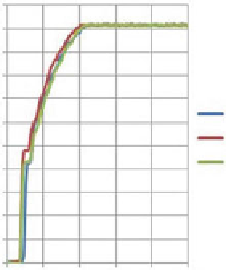
Comparison between the plots of 0
ı
and 90
ı
with the hew test arrangement
Fig. 12
180 degree
270 degree
1100
1000
900
800
700
600
500
1100
1000
900
800
700
600
500
180 degree 1
180 degree 2
270 degree 1
270 degree 2
270 degree 3
180 degree 3
400
300
200
100
0
400
300
200
100
0
0
20
40
time [s]
60
80
100
0
20
40
time [s]
60
80
100
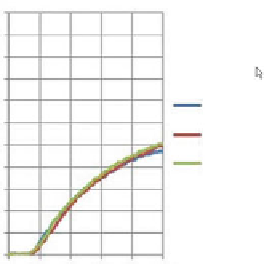
Comparison between the plots of 180
ı
and 270
ı
with the new test arrangement
Fig. 13
compared to the previous ones. Now there is a big difference between the curves of
180
ı
and 270
ı
(Fig.
13
).
Figure
14
shows a new reference system that was adopted in order to create an
easier and simpler code for a proposed measuring/recording programme that would
be used to indicate the possible position and probable size of leak in the “colon”.
It maintains the same previous functions for each inlet and outlet presented in the
testing ring, but with a difference in the angles. Instead of counting from 0
ı
to 270
ı
,
it will be divided in positive side and negative side, going from 0
ı
180
ı
to
C
and
from 0
ı
to
180
ı
.