Biomedical Engineering Reference
In-Depth Information
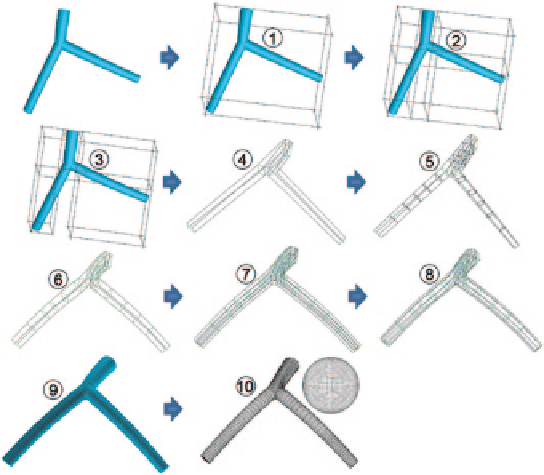
Fig. 6.24
Multi-Block structured mesh flow chart for a left coronary artery bifurcation
5. To better capture the branch curvature, all blocks are split into more sub-blocks
along main branch and sub-branches.
6. The new blocks are associated to the nearest geometry entities, once again to
attain the same curvature as the fluid domain.
7. All blocks are split along the vessel radius-direction to further fit the fluid
domain, and all block edges are projected to the corresponding geometry enti-
ties again.
8. The existing hexa-grid blocking topology is converted to an O-Grid topology,
where a prism layer is created at the near wall region.
9. Based on the dimension of the fluid domain, reasonable node distributions are
defined at each block edge to produce the final mesh.
10. The final mesh results are produced and a close view of inlet mesh is shown.
Apart from idealized models, two selected locations of image-based aortic artery,
aortic arch and Aortic Abdominal Aneurysm (AAA), were meshed using the same
strategy. Figure
6.25
shows the outcome of applying the same steps.
Search WWH ::

Custom Search