Hardware Reference
In-Depth Information
4.
Now you can test your display. Temporarily take a wire from the 0-volt power rail
at the bottom of the breadboard and connect it to the unconnected leg of each
resistor in turn (the leg of the resistor that is not connected to the display).
Every time you touch a different unconnected leg of a different resistor, a differ-
ent segment should light up. Compare the segments against the segment dia-
gram in Figure 5-10, which shows the display I have used in this project, and
make sure your display is internally wired up the same way. If it is different, keep
a note of which segment letters are attached to which resistors, as you will need
to know that later. (See Figure 5-11.)
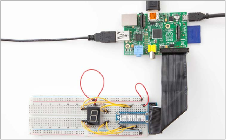
FIGURE.5-11
The 7-segment LED is wired up and ready for testing on the Raspberry Pi.
Once you have tested your display and made sure it's all working properly, the next
step is to connect your display up to your computer's GPIOs so that you can control
each LED from your Python program. For each resistor, run a wire from the uncon-
nected leg of that resistor and connect it to a different GPIO—follow the diagram in
Figure 5-12 for the Raspberry Pi, or use Figure 5-13 if you have an Arduino. If you
discovered with your earlier testing that your display works differently from mine, use
the notes you took earlier when you touched a wire on each resistor leg in turn, and use
this information to wire each segment to the correct GPIO pin of your computer. If
you don't do this, you will get some very strange looking patterns on your display
when you run your Python program!