Hardware Reference
In-Depth Information
3.
Run a wire between the positive power rail at the top of the breadboard, and the
pin on the Arduino labelled as VCC. (VCC is just a technical term that means the
positive power supply, which on your Arduino board is 3.3 volts.)
4.
Run a wire between the negative power rail at the bottom of the breadboard and
the pin on the Arduino labelled as GND. (GND is just a technical term that
means the 0-volt power supply connection.)
Provided your Arduino is powered up, your LED should now light up, as it is being
powered by the power supply of your computer.
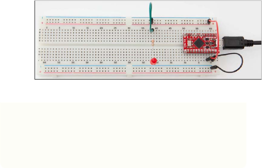
FIGURE.5-9
The Arduino connected to the breadboard
If your LED does not light up, check that it is the right way. Turn it around the
other way to see if it works. You can also check back against the diagram of how
a breadboard is wired up internally, and follow the circuit from the 3.3 volt power
pin, all the way round the circuit until you get to the 0-volt pin, checking that each
connection is made correctly. The usual reason for the LED not lighting up is that
it is in the wrong way, or you have plugged its legs into the wrong holes in the
breadboard so that it is not making a complete circuit.
Flashing the.LED
Now that you know that your LED is wired up properly and working, the final thing to
do is to write a Python program that makes it flash:
1.
Start IDLE, and create a new program by clicking File
➪
New and then save the
program as
testLED.py
.
2.
Import the time module, which you will use to insert a delay between each flash
of the LED.
import time