Graphics Programs Reference
In-Depth Information
to go to edit mode, press
A
to select all the vertexes (if the vertexes are
deselected). Now, press
U
and chose an unwrapping method from the
pop-up menu (
Smart UV Project
and
Cube Projection
don't even need
the seams), then go out of edit mode to update the Rendered preview.
The
Texture Coordinate
node is not needed in the case you unwrap an object and
then use an
Image Texture
node, because in that case Cycles will automatically use
the available UV coordinates to map the image map.
Obviously, the
Texture Coordinate
node alone is not enough. What we need now is
a way to offset, rotate, and scale this texture on the surface:
1. Select the
Texture Coordinate
node and grab it to the left of the window,
as far as suffices to make room for a new node. In the
Add
menu, go to
Vector
and choose
Mapping
.
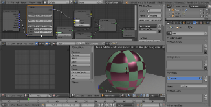
2. Grab the
Mapping
node on the middle of the link that is connecting the
Texture Coordinate
node to the
Checker Texture
node; it will be auto-
matically pasted in-between them, as shown in the following screenshot:
3. Now, start playing with the values inside the
Mapping
node. For example,
set the
Z Rotation
value to
45°
, the
X Scale
value to
2.000
and then
slide the
X Location
value, while looking at the texture changing orient-
ation, dimension and actually sliding on the x axis in the
Rendered
view-
port.
4. Save the blend file as
start_04.blend
.
The
Min
and
Max
button on the bottom of the
Mapping
node are used to clip the
extension of the texture mapping. That is, check both
Min
and
Max
to avoid the tex-
ture to be repeated n times on the surface and shown only once. A minimum value