Biomedical Engineering Reference
In-Depth Information
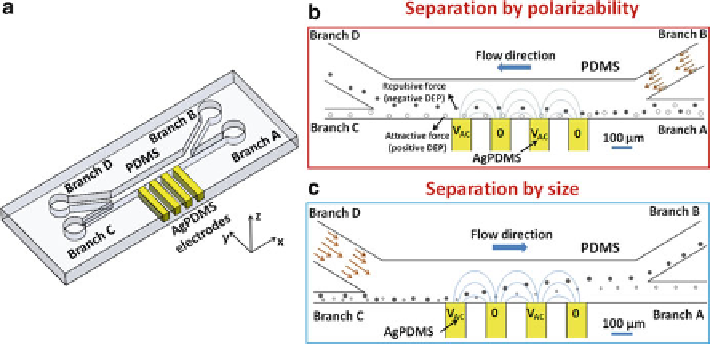
Fig. 11.2
(
a
) Schematic of a PDMS-fabricated microfluidic device with sidewall conducting
AgPDMS composite electrodes. (
b
) Schematic of continuous separation of samples of similar
sizes by polarizability [
23
]. In this operation mode, the device separates the samples under pDEP
to the lower branch C and the others under nDEP to the upper branch D. (
c
) Schematic of
continuous separation of samples of two different sizes but having the same polarizability [
22
].
The device separates larger samples (undergoing a larger nDEP force) to the upper branch B and
smaller samples to the lower branch A ((
a
and
c
) are adapted with permission from Lewpiriyawong
et al. (2010).
2010 WILEY-VCH Verlag GmbH & Co. KGaA; (
b
) is reprinted with permission
from Lewpiriyawong et al. (2011).
#
2011 American Chemical Society)
#
performed in stagnant buffer solutions under a broad spectrum of AC electric field
frequencies (i.e., 10 kHz to 80 MHz). Accommodating this parameter allows for an
investigation of frequency-dependent DEP behaviors of cells, which are useful
information for separating different kinds of cells. In addition to the characteriza-
tion, this device can be operated to separate particles and cells, depending on either
their polarizability or size.
11.3.1 Separation of Samples by Polarizability
Figure
11.2b
illustrates the separation of cells from particles of similar sizes by
pDEP and nDEP forces, respectively, due to their different polarizabilities. In
particular, the samples containing a mixture of cells and particles from branch A
are first hydrodynamically focused by the flow from branch B such that the focused
samples can experience a strong DEP force near the electrodes. Then, the cells
undergoing pDEP are attracted to the electrodes and are transported to the lower
branch C, while the particles undergoing nDEP are repelled away from the
electrodes being transported to the upper branch D.
Search WWH ::

Custom Search