Biomedical Engineering Reference
In-Depth Information
Microchannel
Syringe
pump
High speed
camera
Mirror
PC
Inverted microscope
Confocal
scanner CSU22
DPSS laser
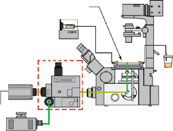
Fig. 9.5
Experimental setup of a confocal micro-PIV system
light source (usually laser) and a high speed camera, as shown in Fig.
9.5
.Ina
confocal system the light enters the CSU and then is conducted to the microscope to
illuminate the sample from below the microscope stage. The light emitted from the
fluorescent trace particles goes back into the CSU and then to a high-speed camera
to capture the confocal images.
9.3.3 Comparison Between Conventional and Confocal
Micro-PIV
Figures
9.4
and
9.5
show the main components of both conventional and confocal
micro-PIV systems. It is clear that the main difference between the two systems is
the existence of a CSU in the confocal system. A study to compare the systems was
performed under the same flow conditions. The flow measurements were performed
in a 100
m glass square micro-channel where pure water seeded with 0.15% of
tracer particles was pressure driven by means of a syringe pump.
Figure
9.6
, clearly demonstrates that by using a CSU it is possible to obtain
much clearer image definition of the individual trace particles. Hence, a confocal
system reduces the out-of-focus background noise and therefore increases the
contrast and definition of an image. By contrast, images recorded by the conven-
tional system were largely blurred, since the out-focus-light reduces contrast and
m
Search WWH ::

Custom Search