Biomedical Engineering Reference
In-Depth Information
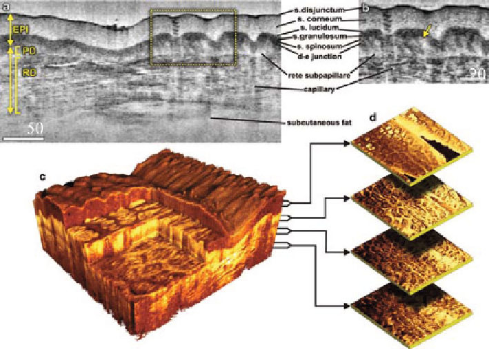
Fig. 8.14
OCT skin images at 1,300-nm (
a
) B-scan of skin above the proximal interphalangeal
joint of the middle finger. (
b
) Magnified view of epidermis and dermis (
yellow arrow
points
towards the dermal-epidermal junction). (
c
) 3D rendering of the same region reconstructed using
1024 B-scans. (
d
) En face sections of the same (Reproduced with permission)
8.5 Coherence Scanning Interferometry
CSI and confocal microscopy can also be considered to be tomographic techniques
and are discussed together in this section because they both provide additional 3D
information that is beyond that obtainable using coherent microscopy and OCT.
This information is the response of the object to illuminating plane waves
propagating at different angles
. Interestingly, both CSI and confocal microscopy
predate coherent microscopy and OCT.
In CSI the object is illuminated by a wide-band distributed source (halogen or
LED) through a Mirau interference objective as shown in Fig.
8.15
.Interference
between the light reflected from a reference surface (within the Mirau objective) and
that from the objective is recorded by the CCD as the object is scanned through focus.
Considering first the distributed nature of the source, the interference fringes
generated by a quasi-monochromatic CSI can be considered to be due to the
superposition of coherent recordings made of different plane waves propagating at
different angles [
21
]. The response is illustrated schematically for five different plane
wave illuminations in Fig.
8.16
.
In practice, if a distributed source and appropriate condenser lenses are used to fill
the aperture of the objective, the TF becomes a continuum within the region shown.
Search WWH ::

Custom Search