Biomedical Engineering Reference
In-Depth Information
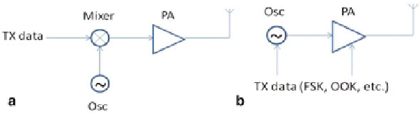
Fig. 8 a
Conventional up-conversion type transmitter.
b
Direct-conversion transmitter
Transmitter Design
The function of a transmitter is to deliver the modulated RF signal to the air with
maximum output power and maximum efficiency. There are different transmitter
structures that can be implemented as the IR-UWB transmitter. The advantages and
disadvantages of each structure are compared below.
Fig.
8
a shows the mixer-based transmitter, which up-converts the baseband data
to the LO frequency. The output of the mixer is amplified to a desired power level
by a power amplifier (PA), and sent to the antenna. This transmitter architecture
can be used with a general purpose modulation scheme in the baseband data, such
as Amplitude Shift Keying (ASK), On-Off Keying (OOK), Frequency Shift Keying
(FSK), Phase Shift Keying (PSK), etc. The disadvantage of this architecture is that
the output power and power efficiency of a mixer are usually relatively low, and this
requires a power amplifier with high power gain and large output power. Furthermore,
due to the spectrum mask requirement, a linear power amplifier is required in order
to preserve the envelope (e.g. triangular or trapezoidal) of the transmitter data. This
further reduces the output power and power efficiency of the transmitter, as compared
to using a saturated power amplifier.
Instead of using the general purpose up-conversion transmitter, there are other
transmitter architectures that can be optimized for the specific modulation scheme,
which achieve a higher output power and power efficiency as in Fig.
8
b. A direct-
conversion transmitter for FSK and OOK modulation in [
9
-
11
] is presented. The
oscillator and power amplifier can be modulated by the baseband data with FSK or
OOK modulation. The power amplifier is directly driven by the oscillator. In com-
parison with the mixer in Fig.
8
a, which uses passive mixer without extra power
consumption (therefore the power consumption is equal), the oscillator usually pro-
vides a large output signal with high power efficiency thanks to the internal positive
feedback. In this way, the input power of the power amplifier is larger as compared
to that in Fig.
8
a, therefore the output power and power efficiency of the transmitter
are increased.
To further improve the output power and efficiency, an injection-locked transmitter
[
12
] can be adopted. As shown in Fig.
9
a, the power amplifier in Fig.
8
b is replaced
by a power oscillator. The reference oscillator provides the LO frequency (with or
without a phase-locked loop or frequency-locked loop). The power oscillator can be
Search WWH ::

Custom Search