Biomedical Engineering Reference
In-Depth Information
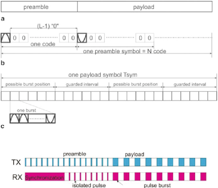
Fig. 5
Structure of
a
15.4a compliant data,
b
preamble symbol,
c
payload symbol
Fig. 6
Transmitted and received enable signal
and can be transmitted in either the first or third quarter. In burst-position-modulation
(BPM) scheme, a data in the first quarter represents “0” and in the third quarter “1”.
The number of pulses per burst (Ncpb) and the duty-cycle ratio determines the data
rate.
In both preamble and payload, data information (contained in pulses/bursts) is not
transmitted/received continuously. Therefore, it is possible to duty-cycle the system
to average down the total power consumption. As shown in Fig.
6
, colored blocks
indicate that the system is switched on and the white indicates it is off. Obviously,
in the transmitter, duty-cycling can be achieved during the whole packet. While the
receiver needs to work continuously first to get synchronization, and thereafter is
duty-cycled by an enable signal generated by the digital baseband.
In order to apply the duty-cycling in the system, a few clock signals will be
needed. A permanent clock will be needed to define the time grid of turning on/off
the system, a LO signal is necessary as in any other transceivers to provide the car-
rier frequency from 6 to 10 GHz with 500 MHz frequency step, and a 499.2 MHz
clock to generate the 2-ns wide pulses in the transmitter and to serve as the sampling
clock in the receiver. In the proposed system, to minimize the design risk and to
reduce the system complexity, the following clock system is chosen. The permanent
clock is chosen at 124.8 MHz, and together with the 499.2 MHz clock are generated
Search WWH ::

Custom Search