Biomedical Engineering Reference
In-Depth Information
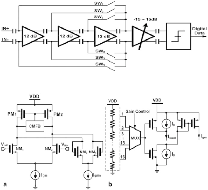
Fig. 8
Schematic of the analog baseband
Fig. 9
Schematic of the
a
g
m
-cell and
b
fine gain control circuit
accurate gain control, closed-loop amplifiers are typically used [
14
,
15
]. However,
a closed-loop amplifier consumes a large amount of current. An alternative way to
achieve accurate gain control is to use the g
m
-ratioed amplifier as shown in Fig.
9
a
at low current consumption [
16
]. The amplifier gain can be approximately expressed
as g
m,in
/g
m,load
, where g
m,in
=
g
m3
−
4
. By proper setting of the
size for transistor M
1
-M
4
, and the current of I
gm
and I
load
, the amplifier gain can be
accurately controlled.
More importantly, the ratios of transistor size and current deviate very little from
the design values in CMOS implementation by proper circuit design and layout
techniques. Both the fixed gain and the fine tuning amplifiers are implemented with
the g
m
-ratioed architecture with different sizes. For the fine tuning amplifier, the
accurate gain step is realized by controlling the current ratio of I
gm
and I
load
in a
logarithmic way. The current steering circuit is depicted in Fig.
9
b. The gain control
signal is generated using a resistor voltage divider. One of the 16 control references is
selected by a MUX, controlled by gain control word from SPI. By a proper selection
of transistor M
7
−
8
sizes and current I
0
, a logarithmic amplifier can be realized based
on the g
m
-ratioed amplifier [
16
].
g
m1
−
2
and g
m,load
=
Search WWH ::

Custom Search