Biomedical Engineering Reference
In-Depth Information
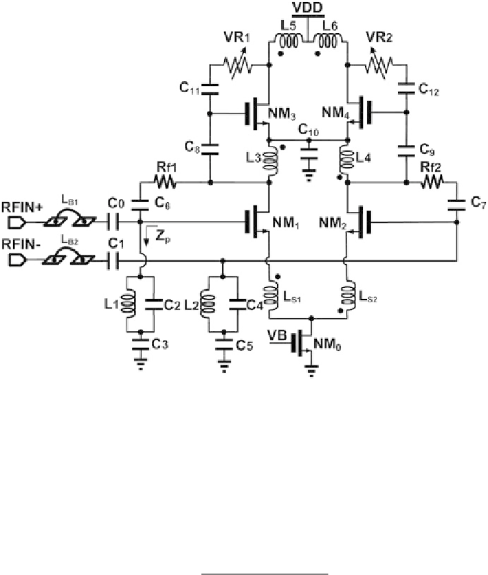
Fig. 5
Schematic of the fully differential low noise amplifier (first and second stages)
A modified LC ladder network input matching network is used for wideband
matching. It should be noted that L
B1
and L
B2
are implemented with bonding wires,
L
1
and L
2
are off-chip high-Q inductors. In addition, the DC decoupling capacitor
is optimized to control the transmission zero position to enhance the out-band inter-
ference rejection around 2.4 GHz. The shunt LC resonant tank input impedance
Z
p
can be expressed as:
1
−
ω
2
L
1
(
C
2
+
C
3
)
Z
p
=
(5)
−
ω
2
L
1
C
2
)
·
(1
jωC
3
The transmission zero can be calculated as:
1
√
L
1
(
C
2
+
ω
p
=
(6)
C
3
)
By optimizing the value of L
1
and C
2
,C
3
, the transmission zero can be used to
attenuate out-of-band interference at 2.4 GHz while maintaining input matching in
3-5 GHz band. As illustrated in Fig.
6
, when C
2
increases from 2 to 4 pF, the notch
frequency decreases from 2.48 to 1.9 GHz.

Search WWH ::

Custom Search