Biomedical Engineering Reference
In-Depth Information
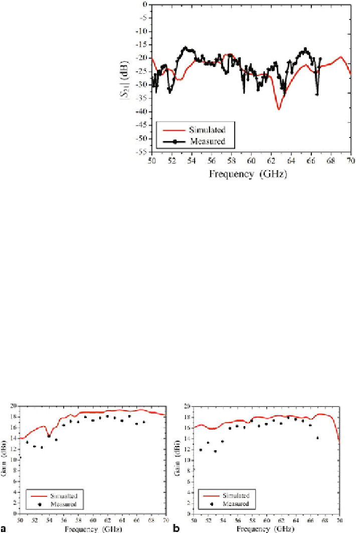
Fig. 33
Measured and
simulated ports isolation
(|
S
21
|) of the antenna array
to coaxial adapter, GSG probes, and misalignment), the accuracy of the measured
gain is estimated to be 1 dB in the frequency band. The simulated and measured
gain results are 18.5 and 17.1 dBi for Port H, respectively. The measured 3-dB gain
bandwidth of the proposed array for Port H is from 56 to 67 GHz. As Fig.
22
b shows,
the simulated and measured gain results are 17.8 and 16.6 dBi for Port V, respectively.
The measured 3-dB gain bandwidth of the proposed array for Port V is from 55 to
66 GHz. compared with the simulated results, the gain is dropped about 1.4 dB.
It is mainly caused by three following reasons: (1) the deterioration of impedance
matching; (2) the deviation of the LTCC substrate dielectric and the conductivity of
the metallization material; (3) The shrinking of LTCC fabrication.
The measured and simulated co-pol and cross-pol radiation patterns of the
proposed dual-polarized antenna array in two principal planes (XoZ-plane and YoZ-
plane) at 60 GHz for Port H and Port V are shown in Fig.
35
, respectively. For
Port H horizontal polarization, as Fig.
35
a shows, the simulated and measured
Fig. 34
Measured and simulated gain of the antenna array,
a
Port H:
horizontal
polarization,
b
Port V:
vertical
polarization
Search WWH ::

Custom Search