Biomedical Engineering Reference
In-Depth Information
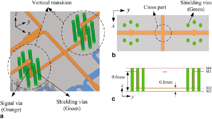
Fig. 26
Configuration of the proposed low-loss cross-over structure.
a
3D view,
b
To p
view,
c
Side
view
and solve the overlap cross of the transmission line. The configuration of the low-loss
cross-over structure is shown in Fig.
26
. The low-loss cross-over structure consists
of two vertical coaxial-like type transmission structures. The signal via connect the
signal line at M2 layer and M3 layer. Surrounding the signal via, six shielding vias
connected the top (M4 layer) and bottom grounds (M1 layer) are used to achieve an
optimum coaxial effect and less low transmission. Figure
27
shows the simulated
S
parameters of the proposed cross-over structure. The simulated |
S
11
| and |
S
22
| are
below
0.4 dB from 55 to 65 GHz.
The SL fed antenna array is almost impossible to test directly. Therefore, two
GCPW-SL transitions were designed as the Port H and Port V of the proposed dual-
polarized antenna array, so that the antenna array can be measured with the probe
station measurement as illustrated in Fig.
28
. For both two different types of GCPW-
SL transitions, a partial middle ground is added lower than the upper ground by
0.1 mm (1 LTCC layer) to facilitate probe pitch touching. For the Port H GCPW-SL
transition, the simulated |
S
11
| is below
−
20 dB and |
S
21
| is less than
−
0.3 dB from
50 to 70 GHz. While, the simulated performance of the Port V GCPW-SL transition
is |
S
11
|
<
−
15 dB and |
S
21
| is less than
−
−
18 dB and |
S
21
|
>
−
0.25 dB from 50 to 70 GHz.
The Mechanism for Performance Enhancement of Antenna Array
by Loading the Open-ended SICs Structure
The electric distributions on the top surface of antenna array for Port H and Port V
are simulated by HFSS software are shown in Figs.
29
and
30
, so as to investigate
the mechanism for performance enhancement of the antenna array loaded by the
open-ended SICs structure. When the antenna is fabricated on a large size substrate
Search WWH ::

Custom Search