Biomedical Engineering Reference
In-Depth Information
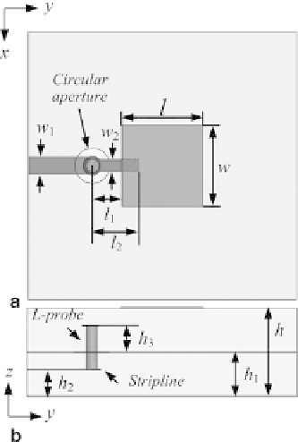
Fig. 4
Geometry of the
LTCC L-probe patch element.
a
To p
view,
b
Side
view (from
[
10
], reprinted with
permission from IEEE)
Following the fabrication process requirement, the diameter of each via is 0.1 mm,
and the distance between the centers of two adjacent vias is 0.25 mm. In this work, the
element spacing of
d
λ
0
) was chosen. The total size of the proposed
antenna array excluding the measurement transition is 14.4
=
3.7 mm (0.75
1mm
3
.
×
14.4
×
Single L-probe Patch Radiating Element
The single L-probe patch antenna element is shown in Fig.
4
. The multilayer LTCC
substrate used is Ferro A6-M with dielectric permittivity
ε
r
=
5.9 and loss tangent
δ =
=
tan
0.01 mm. The L-probe is constituted
by a vertical via and a horizontal microstrip line. The proposed antenna element is
fed by a SL to suppress the radiation from the feeding line. The detailed dimensions
are shown in Table
1
. The total thickness
h
is 1 mm (10 LTCC layers) including
five LTCC layers (0.5 mm) as the SL feeding part and five LTCC layers (0.5 mm)
as the antenna part. The width
w
1
of the feed SL was chosen to be 0.15 mm, which
corresponds to the characteristic impedance of 50
. The via diameter is 0.1 mm.
Figure
5
shows the simulated impedance bandwidth and gain of the proposed
antenna element by HFSS. The simulated impedance bandwidth is about 50.4 %
with respect to the center frequency of 61.5 GHz from 46 to 77 GHz for |
S
11
|
0.001. The conductor thickness is
t
≤−
10
dB. The simulated gain is 5.7 dBi at 60 GHz.
Search WWH ::

Custom Search