Biomedical Engineering Reference
In-Depth Information
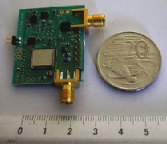
Fig. 17
UWB transmitter
integrated with a narrowband
(NB) receiver
much lower because it is programmed to operate in sleep mode operation using the
control commands by the microcontroller. In this manner, it is possible for the coor-
dinator node of the network to send control commands to the sensor node, allowing
several sensor nodes to operate in a coordinated network. The microcontroller will
be in charge of the data reception and transmission. It will configure the transmission
parameters, such as pulses per bit value and PRF, based on the information received
through the NB feedback path. Figure
17
depicts the implementation of the sensor
node in a PCB. The board dimensions are 30 mm (L)
×
25 mm (W)
×
0.5 mm (H).
UWB Reception
The block diagram of the receiver circuit is shown in Fig.
18
[
39
]. The signal entering
the receiver passes througha3to5-GHz BPF to eliminate the unwanted interfering
signals. The filtered signal is then amplified by 48 dB using three wideband LNAs
before down-converting to a baseband signal using a mixer and a 4-GHz VCO. The
Fig. 18
UWB receiver architecture

Search WWH ::

Custom Search