Biomedical Engineering Reference
In-Depth Information
Type I
Type II
Type III
a
b
c
20 K
20 K
20 K
120
120
120
180
180
180
200
220
225
d
e
f
20 K
20 K
20 K
120
120
120
180
180
180
200
220
225
1.0
1.1
1.2
1.3
1.0
1.1
1.2
1.3
1.0
1.1
1.2
1.3
Energy (eV)
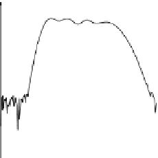
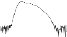
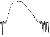
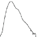
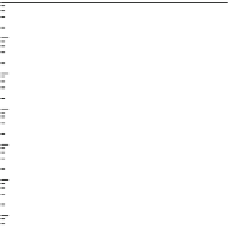
Fig. 3.10
Temperature-dependent PL of chirped QDM bi-layers: measured PL spectra of Types
(
a
)I,(
b
) II, and (
c
) III; simulated PL spectra of Types (
d
)I,(
e
) II, and (
f
) III. Line spectra in (
a
-
f
)
are offset for clarity. Simulated line spectra in (
d
-
f
) are performed at the same temperatures as the
measured spectra in (
a
-
c
), respectively. Adapted from [
23
]
This is not to be taken as a limiting factor for room-temperature operations as the
structures have yet to be optimized. The overarching trend in all samples is the
subsequent quenching from the high-energy ends. In Fig.
3.10
a, for example, the
highest-energy peak at 1.214 eV is the first to be quenched, followed by the next
immediate peak at 1.086 eV, and finally by the lowest-energy peak at 1.048 eV. Such
orderly quenching is characteristic of thermal activation of carriers out of QDs into
the adjacent WL and/or GaAs matrix where carriers recombine non-radiatively. The
multiplicity of luminescent peaks in the QDM bi-layers makes it difficult to identify
the NRR channels and associated activation energies without prior knowledge from
controlled single QDM layer structures. If our hypothesis of optical independence
between the QDM bi-layer is correct, the main escape channel should be the same
as QDM single layers, i.e. the WL as identified by the Arrhenius plots in Fig.
3.8
.
In order to identify the NRR channels and to understand the temperature
dependencies of the three chirp structures, the spectra are fitted to the equation:
2
4
i
=
1
i
I
i
exp
(
E
−
E
i
)
/
Γ
I
=
1
+
A
exp
−
(
E
−
E
WL
)
/
η
i
k
B
T