Biomedical Engineering Reference
In-Depth Information
a
b
T
(
E
)
T
(
E
)
1
1
Φ
= 0
Φ
=
Φ
0
/4
1
1
10
-2
10
-2
10
-2
10
-2
10
-4
10
-4
-6
-6
10
-4
10
10
-4
10
1.9
2.
2.1
1.9
2.
2.1
10
-6
10
-6
12
E
12
E
-2
0
2
4
6
8
10
-2
0
2
4
6
8
10
c
d
T
(
E
)
T
(
E
)
1
1
Φ
=
Φ
0
/2
Φ
=
Φ
0
/2
1
1
10
-2
10
-2
10
-2
10
-2
10
-4
10
-4
-6
-6
10
-4
10
10
-4
10
1.9
2.
2.1
1.9
2.
2.1
10
-6
10
-6
12
E
12
E
-2
0
2
4
6
8
10
-2
0
2
4
6
8
10
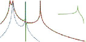
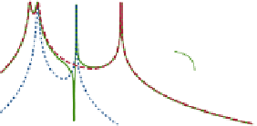
Fig. 8.5
Transmission for the connection (1,3) as a function of the Fermi energy for an asymmetric
ring with hopping parameters
t
12
=
t
23
=
0
.
2(
upper arm
),
t
34
=
t
41
=
1(
lower arm
), and on-site
energies
4(
solid line
), as compared to the transmissions through the upper arm only
(
dotted blue line
), and throughout the lower arm only (
dashed red line
). Figure (
a
)-(
c
) corresponds
to a decoupled ring (
V
ε
=
2and
ε
=
2
2
=
0) (
a
) at zero magnetic field, (
b
)at
Φ
=
Φ
/
4, and (
c
) magnetic flux
0
Φ
=
Φ
/
2. Figure (
d
) has an interarm coupling
V
=
0
.
5 and magnetic flux
Φ
=
Φ
/
2. The
insets
0
0
show in more detail the behavior of the curves around the resonance
because they do not enclose any magnetic flux and, therefore, are not affected by
Φ
.
In panel (d), the connection between the arms was switched on (
V
=
0
.
5), which
affects the position of the peaks and dips.
In Fig.
8.5
, the four peaks of conductance, corresponding to connection (1,3),
can be recognized as those from the lower arm along with the on-site energy of
site 2. The transmission of the ring nearly coincides in almost the whole range
with that of the lower arm, thus showing that the conduction is throughout such
a pathway at almost every energy, except for
E
≈
ε
2
. When the incident electron is
resonant with the site 2, the transmission is well described by the resonant peak of
the upper pathway. Nevertheless, none of the paths by themselves can provide the
onset of the antiresonance close to
E
A
13
B
13
B
13
≈
ε
2
. The self-energy
Σ
13
=
Σ
+
Σ
≈
Σ
A
13
t
up
/
(
B
13
t
down
/
(
because
Σ
=
E
−
ε
2
)
Σ
=
E
−
ε
4
)
, except for
E
≈
ε
2
when they
can become comparable. Hence, in a neighborhood of
E
≈
ε
2
, the self-energy
t
up
/
(
t
down
/
(
ε
2
−
ε
4
)
can be approximated as
Σ
13
=
E
−
ε
2
)+
which vanishes for
t
up
(
ε
4
−
ε
2
)
/
t
down
, that is, slightly to the right of the peak
E
E
=
ε
2
+
=
ε
2
, thus
giving the Fano-like profile.
The Fano-like peak shows the signature of the interference between both paths,
typical when a localized state interferes with a continuum. Figure
8.5
a-c shows the
dependence of the Fano profile with the magnetic flux. With no magnetic flux, there