Biomedical Engineering Reference
In-Depth Information
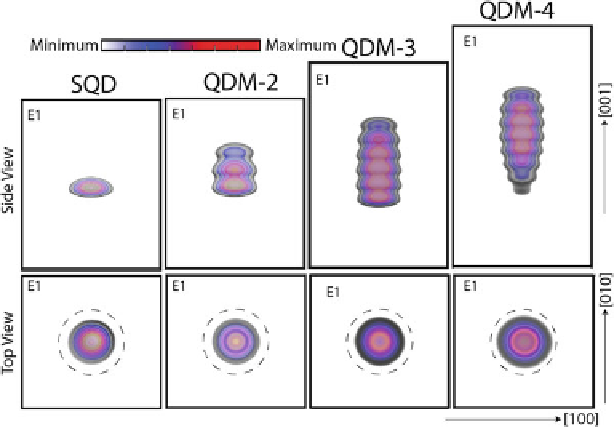
Fig. 5.4
Plots of the lowest conduction band state,
E
1
, for the quantum dot systems SQD, QDM-
2, QDM-3, and QDM-4.
First row
: the side view of the plots is shown.
Second Row
: the top view
of the plots is shown. The intensity of the color in the plots indicates the magnitude of the wave
function: the
red color
represents the highest magnitude and the
light blue color
represents the
lowest magnitude. The
dotted circles
are marked to guide the eye and indicate the boundary of the
base of each QD
the valence band states as the size of the QDM increases, in consistent with our
earlier discussion regarding the reduced biaxial strain implies enhanced HH-LH
intermixing. This also suggests that the TM mode will increase for the QDMs as a
function of their size (the number of the QD layers) due to the larger LH character
of the valence band states, as will be shown by our calculations later in Sect.
5.4.1
.
5.3.3
Electron Wave Functions form Molecular States
Before we move to the study of the polarization properties of the QDMs, let us first
analyze the nature of the electron and hole states. Figure
5.4
shows the plots of the
lowest conduction band state
E
1
for the four QD systems: SQD, QDM-2, QDM-3,
and QDM-4. From the top views of the wave functions (second row), it is evident
that the lowest electron state is of s-type symmetry. The side views of the wave
functions (first row) show that the electron states form hybridized (molecular) states
in the QDMs and are spread over all of the QD layers. This is due to the strong
coupling between the QD layers at 4.5 nm separation. The presence of the s-like
electron wave function in all of the quantum dot layers implies that only the details
of the hole wave functions inside the QDM will determine the optical activity of a