Biomedical Engineering Reference
In-Depth Information
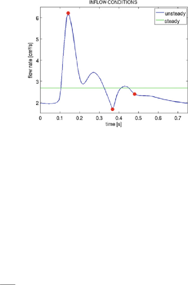
Fig. 6
Steady and unsteady inflow flux profiles versus time. The
points
indicate locations of “peak
systole,” “minimum diastole” and “mean diastole” used in the discussion section
In the case of pulsatile flow simulations for the idealized geometry, a periodic
wave inflow boundary condition is imposed, representing a realistic heart beat
waveform, in the carotid, with a mean flux equal to the steady-state flux value. The
steady and unsteady inflow flux profiles with respect to time are illustrated in Fig.
6
.
Convergent steady-state and pulsatile solutions were identified by checking that
the difference between two consecutive time steps (steady case) or two consecutive
cycles (unsteady case) was negligible. In the case of the steady state solutions this
convergence is of the order of 10
−
7
, while for the unsteady case all the results
presented correspond to the 12th cycle where the convergence is of the order of
10
−
6
.
The steady-state simulations were carried out using a time step of 0
.
01 s, while
the pulsatile used a time step of 0
0075 s, corresponding to a hundredth of the heart
beating period. Moreover, a time step of 0
.
10
−
4
s was taken when the coupling
with the 1D hyperbolic model is used as outflow boundary condition. For both 1D
a
nd
0D models, the
.
5
×
β
parameters used were determined through expression
β
=
√
π
h
0
E
2
, where the thickness of the wall
h
0
was set to 10 % of the vessel radius,
the Young modulus was set to
E
1
−
ξ
10
5
, and the Poisson ratio was set to
=
ξ
=
0
.
5,
assuming the artery wall is incompressible.
A volumetric mesh of about 0
85
M
tetrahedra was created for the anatomically
realistic geometry, corresponding to a graded mesh with element size of 0
.
.
016 cm
within the aneurysm, and maximum size of 0
04 cm in the upstream and downstream
sections. The idealized geometries are planar with the parent vessel radius of
.
Search WWH ::

Custom Search