Biomedical Engineering Reference
In-Depth Information
Fig. 2.
Integrated system
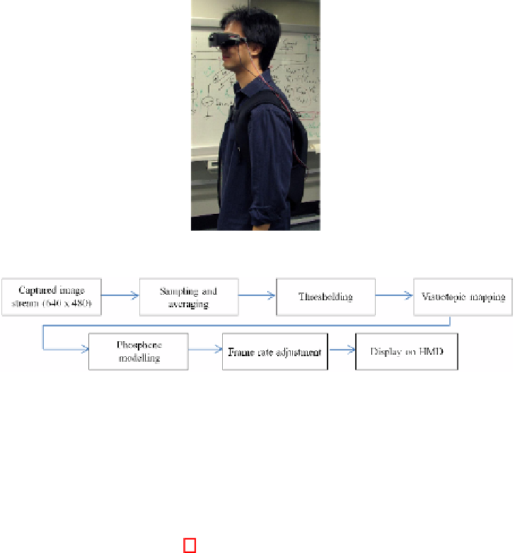
Fig. 3.
Flowchart of main functions of the system
are fastened inside a hard plastic laptop casing, which is then placed in a neoprene lap-
top bag with cables running to the camera and HMD that the user is wearing. A 12V
rechargeable lithium-ion battery pack is used to power the system.
3
System Implementation
The flowchart shown in Figure 3 outlines the implementation of the main functions of
the HatPack. A high resolution image stream (
640
×
480
pixels) is captured by the
CMOS camera, which is delivered to the DE2-115 development board via a standard
NTSC analogue connection. After decoding of the NTSC signal is complete, the pixels
are sampled and averaged. The sampled data is thresholded in order to simulate pos-
sible limitations of electrode stimulation. A pre-generated visuotopic mapping lookup
table is then used to determine the placement of the phosphenes on the output display.
A discrete Gaussian falloff profile is used to simulate the physiological phenomena of
a phosphene dot in the visual field. Before output on the screen, the frame rate of the
system can be set in real-time in order to simulate varying stimulation frequencies of
electrodes. A more detailed explanation of these main system features is given in Sub-
sections 3.1, 3.2, 3.3, 3.4, 3.5, and 3.6.
Furthermore, features such as edge detection, histogram assisted threshold selection,
and dead electrode simulation, have been implemented in order to allow for evaluation
of the effects of such image processing techniques on the perception of the provided
low resolution data (Subsection 3.7).
Search WWH ::

Custom Search