Biomedical Engineering Reference
In-Depth Information
2.4
Electron Microscop
py Study of Electrode Encapsulation by Tissue
Concentric bipolar microele
pole diameter of 250 µm (C
STN of two anesthetized ra
current pulses with a repet
250 µA with a stimulus gen
electrodes were removed an
EDTA (1x) in HBSS W/O
other electrode was postfixed
Electrodes were washed
fixed in 1% osmium tetrox
drying (EMITECH K850, A
loidal gold using a Sputter
before examination with a
kochen, Germany).
ectrodes with an inner pole diameter of 75 µm and an ou
CB CSG75; FHC, Bowdoinham, ME) were placed into
ats. The rats were stimulated for 3 h with biphasic const
tition frequency of 130 Hz and pulse duration of 60 µ
nerator (Multichannel Systems, Reutlingen, Germany). T
nd one electrode was incubated in trypsin solution (Tryp
CA&MG W/EDTA.4NA, Gibco, UK) at 37°C for 1 h. T
d overnight in 4% glutaraldehyde (Merck, Germany) in PB
d, fixed in 4% glutaraldehyde in PBS, washed again, po
xide, dehydrated in acetone, and subjected to critical-po
Ashford, Kent, UK). The samples were sputtered with c
r Coater (BAL-TEC SCD 004, Schalksmühle, Germa
scanning electron microscope (DSM 960 A, Zeiss, Ob
uter
the
tant-
s at
The
psin-
The
BS.
ost-
oint
col-
any)
ber-
3
Results
3.1
Electrode Implanta
ation
We implanted 36 Pt/Ir ele
Parkinsonian rats and comb
This allowed for stimulatio
the rats to an apparatus. Fo
riments; we measured in pi
the electrode impedance al
the implanted unipolar elect
Verification by Ink Inject
the target region was verifi
approximately the same siz
ctrodes (15 unipolar electrodes, 21 bipolar electrodes)
bined the bipolar electrodes with chronical instrumentati
on under spontaneous movement conditions without fix
or an optimal adjustment of the DBS signal in future ex
lot tests (without chronical instrumentation) the kinetic
lterations caused by adherent cell growth at the surface
trodes.
tion.
As a first test, the localization of the electrode tip
fied by ink injection via a 5 µl Hamilton micro syringe
e as the implanted stimulation electrode (Fig. 3).
) in
ion.
xing
xpe-
s of
e of
p in
e of
g an
mis-
with
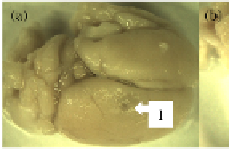
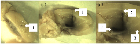
Fig. 3.
Rat brain fixed in form
electrode canal (1), (b): sagitt
phere where tissue was remov
the ink injection canal (2), stria
malin, (a): top view of a rat brain with a puncture resembling
tal section of one hemisphere with the puncture (1), (c): hem
ved to display the injection canal, (d): enlarged photo of (c) w
atum (3), and other parts of the basal ganglia (4)
Counter-electrode Implan
were pierced through the in
stimulation electrode. In a f
ntation.
For the EIS measurements, counter-electro
ntact scalp close behind the cut for the implantation of
first step, a dental wire of biocompatible steel alloy used
odes
the
d as

Search WWH ::

Custom Search